Soviet ICBM Silos | |||
|
|
| ||
| Type I | R-7 / SS-6 | ||
|---|---|---|---|
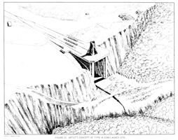
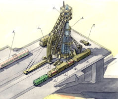
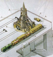
A first-generation site with a single rail-served pad similar to those at Launch Complex A, Tyura Tam. Operational sites of this type were observed only at Plesetsk. Probably the most unusual launch complex was designed for family of R-7 missiles. Firstly, this is the only complex in which the rocket does not stand on the table, but is suspended from the middle. Secondly, in early versions, the starting table rotates entirely before launching. Well, in the third place, instead of the service tower, two "half-tower" are made, which, moreover, depart from the rocket by turning in a vertical plane. Why were such decisions made? The solution to the first point is very well described in B.E. Chertok. The first and second stages of the R-7 missiles are assembled in a package. And this package was very poorly installed on the launch pad - a serious increase in the tail section was required, and this was overweight, and the wind resistance increased. Even there were ideas to build a wall around the start. The sketch of the transport device, which took out the rocket and put it on four starting tables, one for each side block, also did not inspire anyone. And then a very beautiful engineering idea arose. In flight, the forces of the side blocks are transmitted to the central unit through their upper parts. So why not hang the missile at the start for the same power units? In this case, the rocket at the launch is experiencing the same load as in flight, and no special measures are needed to strengthen the structure.
| |||
 |
 |
  |
|
| Type IIA [Soft] | R-16 / SS-7 | Sheksna-N 8P864 | |
A second-generation site with two road-served soft pads similar to those at Launch Complex C, Tyura Tam, prior to the addition of a third launch pad. This type was first observed at Yurya and subsequently at several other locations. Two modifications of the basic configuration were also observed. Initially, the R-16 / SS-7 launch complex was planned on the ground (there was no talk of silos ["mines"] at that time), mobile, i.e. with the use of automobile chassis. But the studies showed that such a complex turned out to be too cumbersome. After that, the mobile complex R-16 was redesigned to the stationary ground combat launch complex 8P864 (Sheksna-N). At the base of the Sheksna-N complex, there were mobile rocket transporters, rocket installers, refuelers of missiles on automobile chassis. At the same time, a reinforced command post (KP) of an excavated type appeared on the BSP, various shelters, 2 starting positions of an open type with starting tables, concrete pads and roadways for the arrival of transporters, installers and tankers. The installation and testing complex (MIK) was also designed in which the missile operations of the missile were carried out, as well as the storage of 3 missiles, there was another separate storage for the missile. The main drawback of such a ground complex in the conditions of a nuclear strike was its vulnerability. The ground launch complex included a combat position with two launching devices, one common command post and a rocket fuel storage facility. the rather complex operation of raising the 8K84 rocket onto the launch pad, which took about two hours, including transportation time from the MIK building. On the left is a MAZ-535 artillery truck with the 8T139 rocket transport trailer - on the right another MAZ-535 artillery truck with the 8U221 installation trailer, parts were raised before the 8T139 rocket transport trailer was erected with the rocket itself , The two trailers thus acted as support towers. The refueling was done with the oxidizer tanker 8G134 and the fuel tanker 8G140, then the two trailers were lowered and transported away, the rocket was now on the launch pad ("start-table") 8U222. The rocket was launched after its installation on the launch pad, refueling with rocket fuel components and compressed gases, and conducting targeting operations. All these operations took quite a long time. The refueling and removal of the trailer took about 1 hour and 30 minutes. To reduce it, four degrees of technical readiness were introduced, characterized by a certain time before a possible start, which needed to be spent to perform a number of operations for the prelaunch preparation and launch of the missile. The R-16 ICBM could be launched in the highest degree of readiness in 30 minutes. The rocket could be fired in about 10 minutes (later reduced to about 5-6 min). The rocket could stay fueled for 30 days. Like all the first-generation missiles, these ICBMs could not stay in the tucked-in state for a long time. In constant readiness, they were stored in shelters with empty tanks and it took considerable time to bring them into readiness for launch. Of more than 6,000 images captured by US satellites of ground-based launchers in the 1960s, only about 2% actually show the R-16 on the takeoff table, indicating that the R-16 (ground-based) rockets are always at a low level were kept in readiness, after 1970 missiles were more or less never seen on the launch tables, except for rare exercises.
| |||
![Type IIA [Soft] - CIA layout](images/site-type-ii-a-image01-s.jpg) |
![Type IIA [Soft] - CIA Diagram](images/site-type-ii-a-image02-s.jpg) |
 |
|
| Type IIB [Soft] | R-16 / SS-7 | ||
| |||
![Type IIB [Soft] - CIA layout](images/site-type-ii-b-image01-s.jpg) |
![Type IIB [Soft] - CIA Diagram](images/site-type-ii-b-image02-s.jpg) |
 |
|
| Type IIC [Soft] | UR-100K / SS-11 | Dolina / Desna-N / Romashka | |
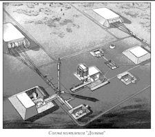
Initially, the rocket was developed in a version with open ground launch, but in 1960 the development of a launch complex with silo launchers was started. In total, three versions of launch complexes were developed - ground "Desna-N" and "Dolina" ["Valley"] and silo "Desna-V". This type of launch site, initially designated Type IV, was another modification of the Type II site and was later designated as Type II (Mod c). This soft configuration consisted of two road-served launch pads. This configuration was first observed at Tyumen and subsequently at other confirmed ICBM complexes. Although it is a soft, road-served installation, if differs from type II as follows: (1) the pad separation is on the order of 870 feet instead of 980 feet; (2) there is a 'plus sign' pattern to the rear of the pad area at most of the sites which may possibly be related to guidance; (3) the ready buildings are about 820 feet from the pad, and are somewhat smaller (ll5 by 140 feet) than ready buildings noted at the Type II sites. The Desna-N complex consisted of two launchers, a buried command post, storage of rockets and fuel components and a radio control point. Complex "Valley" was similar in composition, but it was equipped with an automated start preparation system that allowed launching within 20 minutes. During this time, the rocket was exported from the storage facility, its installation on the ground launch facility, refueling, preparation of the control system and aiming. The minimum interval between launches of missiles from neighboring launchers was 9 minutes, and between re-starts with one PU-2.5 hours. The technological cycle of launch preparation was not sufficiently automated, which extended the process of preparation for launching, required a qualified combat calculation. The process of installing the rocket on the launch pad was complicated and time-consuming, the fuel components were not fast enough to fill, the launch preparation time was almost 2 hours. All this led to the fact that the Desna-N launch complex was not recommended for use in armament. the Desna-N complex was rejected not because of gross structural miscalculations. The high combat and operational characteristics of the R-9A missile, confirmed by the LCI, required the creation of an even more advanced launch complex with a higher combat readiness; It was necessary to approach the rocket and the launch complex as a single whole. OKB-1 became the main organization and the main ideologist of the creation of a new complex of ground-based equipment for the R-9A missile. A new transitional frame was designed and manufactured, with a mass 3 times smaller than the previous one. In the CDB of transport engineering, an effective device was created, controlled by one operator, capable of placing the rocket on the launch pad for 30 seconds. It was possible to bring the readiness time of the R-9A to start, counting from the horizontal position, to 20 min. The new starter complex was called the "Valley". Further reduction of the ready-to-run time was limited by the time for the unwinding of the gyro devices (up to 60,000 rpm). This process took 15 minutes. Work at the Baikonur range to create the Dolina complex was an unprecedented pace: in May 1962 a decision was made to upgrade the Desna-N complex, and at the end of September the construction and installation of a new launch complex " Valley". On February 22, 1963, the first rocket launch from this launch complex was successfully carried out. Observers of that time were struck by the fact that automation provided almost complete absence of combat calculation. The self-propelled cart with the rocket, coming out of the assembly and testing building and reaching the stops on the launch device, was connected to a lifting and mounting device that raised it to a vertical position, automatically docked all communications and fixed the rocket on the launch pad. Then followed the high-speed refueling of rocket fuel components, preparation of the control system and aiming. Everything took 20 minutes instead of 2 hours at the Desna-N complex.
| |||
![Type IIC [Soft] - CIA layout](images/site-type-ii-c-image01-s.jpg) |
![Type IIC [Soft] - CIA Diagram](images/site-type-ii-c-image02-s.jpg) 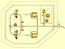
|
  |
|
| Type IID [Soft] | R-16 / SS-7 | ||
| |||
![Type IID [Soft] - CIA Site Map](images/site-type-ii-d-image01-s.jpg) |
![Type IID [Soft] - CIA Diagram](images/site-type-ii-d-image02-s.jpg) |
||
| Type IIIA [Hard] | R-16 / SS-7 | Sheksna-V 8P864 | |
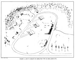
An ICBM launch site configuration observed at a number of confirmed complexes probably represented the initial attempt by the Soviets at site hardening. The evidence indicated that there were probably two silo-type launchers and a control bunker at each site. The degree of hardening had not been resolved, although it was believed on the order of 300 psi. It was further believed that the missile system for the hardened configuration was the SS-7. Beginning in May 1960, experimental design work was carried out related to the launch of a modified R-16U rocket from a silo launcher. In January 1962, the first rocket launch from the silo was conducted at the Baikonur training ground. On February 5, 1963, the first missile regiment (Nizhny Tagil), armed with the DBK armed with these ICBMs, was put on combat duty, and on July 15 of the same year the complex was adopted by the Strategic Missile Forces. The silo for the R-16 missile was developed by TsKB-34 (Chief Designer EG Rudyak). While developing a silo for the R-16U, Yevgeny Rudyak first proposed to install a steel launching cup in the mine. At the bottom of the concrete shaft of the mine there was a rotary starter table, on which a rocket with docked communications of the filling system was installed. On the rocket were installed yoke for movement in the shaft along the guides, as well as for depreciation. When rocket engines started, hot gases went into the gas pipe between the barrel of the mine and a special metal glass that protected the rocket. At the top of the mine, the gas outlet had an expansion and guide vanes for removing hot gases to the side in order to reduce the thermal impact on the rocket. The Sheksna-V silo, in fact, had the same infrastructure as the ground Sheksna-N, but with one exception. It had 3 shafts completely hidden in the ground. The storage of the R-16U rocket in the mines was carried out in a non-refueled state. As part of the launch complex, there was a centralized refueling system with common (for all three mines) storages and pumps for each component of the fuel and remote control of the refueling from the command post. The Sheksna V group rocket complex with the 8K64U missile was deployed in much smaller quantities, since the construction of the mine complexes required more time than for commissioning the spacecraft with ground-based missiles, and also required many technical problems. The construction was conducted in an open manner. The launch complex consisted of three missile silos with a diameter of 8.3 m and a depth of 45.6 m. The mines were lined up in a line and stood at a distance of 65 meters from each other. Nearby, in the underground facilities, there were fuel stores and a command post. All three missiles were fueled centrally, with the help of a high-speed fueling system, from the same tanks-the components (separately fuel and separately oxidizer) of rocket fuel (MCT): nitric acid AK-27I (oxidant) and NDMH-heptyl (fuel) and drainage systems components. The Shaksna missile system with R-16U ICBMs (the first regiment entered combat duty on February 5, 1963 near Nizhny Tagil) and R-9A (the first regiment entered combat duty on December 26, 1964 in the vicinity of Kozelsk) had three silos, located in a line at a distance of several tens of meters from each other, a common underground command post, storage of fuel and oxidizer, and other auxiliary facilities. The R-16U rocket was installed inside the silo structure on a special rotary launcher with docked communications of the filling system. When firing a rocket, the R-16U moved along the guides in the silo. To guide the rocket in the azimuth, the flue was made rotary, it rotated together with the rocket and the launching device. The missile systems with ICBMs R-16 and R-16U were put on combat duty by 1965 under the towns of Bershiet of the Perm Region, Nizhny Tagil (Verkhnaya Salda) of the Sverdlovsk Region, Bologoe (Vypolzovo), Kaliningrad Region, Itatka, Tomsk Region, Yoshkar-Ola of the Mari ASSR , Novosibirsk, Plesetsk ("Angara" facility), Shadrinsk of the Kurgan region, Yurya of the Kirov region and near Tyur-Tam (near the NIIP-5 test site). By the beginning of the seventies, the means of protection looked as follows. Firstly, there are three or four rows of barbed wire fences on high concrete poles, with watchtowers at the edges of sectors and paired patrols between the rows. Secondly, they are sets of electromechanical guarding devices "Tantal" with capacitive signaling "Zone" and sensors SD-30. Thirdly, it is electrified barriers P-100, representing a four-meter thin grid, installed at an angle between two internal rows of fences. An electric current of about four hundred volts was passed through it. When announcing the alarm, the "combat mode" was switched on with a voltage of about one thousand six hundred and fifty volts. Every day, for inspection of the "grid" guard and guard platoon, electricity for a while was turned off. Each of those who went to the fence area received a token and was marked in a special magazine, and before the electricity was switched on, they checked the exit of the personnel from the zone. When carrying out maintenance, the calculations also received a token. Before starting to apply voltage to the grid, that all left the territory (by tokens). With the permission of the commander of the duty forces, he applied tension and put the object under guard. The sergeants were in charge of the guards. Then, in the fourth place, they are mine-blasting fences "Cactus". Mine fields "covered" the launch pad. There were only three fields. Each field consisted of 20 minutes. Only 60 min (type POMZ) on each BSP. Mines exploded in pairs. The distance between the mines is about 5 meters. On the field came the ends of the electrical wiring, detonators were attached to them. The legendary "grid 100" with a voltage of 1650 V is the only system at the time that worked. Mine fields - dummies of wood, painted in black, dressed on pegs. On the desk of the attendant - the lamps of indication were on. But it was a complete fiction. The smoke system was similar. | |||
 |
 |
 |
|
| Type IIIB [Hard] | R-9 / SS-8 | Desna | |
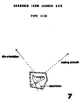
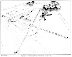
The silo launch complex Desna with the R-9A missile (8K75) was created at the GSKB Spetsmash (later the KBOM) under the leadership of V.P. Barmin missile, R-9A missile in OKB-1 (since 1966 OKB-1 became known as the Central Design Bureau of Experimental Mechanical Engineering - TsKBEM) - under the guidance of S.P.Korolev. The Desna-V mine complex consisted of three silos, located in a single line not far from each other, an underground command post, underground storages of fuel components and compressed gases and a radio control point. The silo launchers of the complex had a depth of 36 m, an internal diameter of 7.8 m with an internal diameter of a glass of flues 5.5 m. The "Desna-V" complex was the first to solve the task of launching oxygen rockets directly from the silo. The Desna V complex consisted of three silos located in close proximity with each other and the underground command center. Underground of propellant components and compressed gases depots and a radio control complex were also in the immediate area. The silos were located 36 meters deep with a minimum diameter of 7.8 meters and a canister diameter of 5.5 meters. The hot launch of a missile from the silo was accomplished by using liquid oxygen cooled to -186°C. The missile could be held in readiness up to 1 year, and in the fueled condition up to 24 hours.
| |||
 |
 |
 |
|
| Type IIIC [Hard] | R-36 / SS-9 | ||
 |
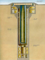

|
||
| Type IIID [Hard] | UR-100K / SS-11 | ||
|
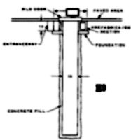
Sixty silos at two Soviet SS–11 complexes (Derazhnya and Pervomaysk in western USSR) were compatible with the SS–19 and others there were being modified by 1973. The Soviets have 180 launchers at these two sites. However, the newer modifications did not appear to include deepening so they may be intended for the SS–17 or SS–11 Mod III. In addition, the Soviets could deploy MIRVed SS–19s–17s at ten other SS–11 sites in the USSR with 50 to 120 SS–11 launchers at each site (any SS–17 deployment would have to be counted as a MIRVed ICBM). The US was confident that the SS–19 cannot be fired from SS–11 silos without detectable silo modification and there is surmise but not hard proof that some changes would be required for the SS–17 as well. | |||
 |
 |
 |
|
| Type IIIE [Hard] | RT-2 / SS-13 | ||
|
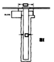
According to Russian sources, the silo itself had a bold design for its time without gas channels. The rocket was inserted into the launch platform [Rus, startovyj stakan, lit: "starting cup"], relying on it with special seals that were discarded after the start. There were no holes in the launcher. To reduce the temperature at start-up, water was poured into the bottom. As a result of the deletion of the gas outlet, the diameter of the silo has significantly decreased, which means its security has increased - a smaller silo is more difficult to damage and easier to protect than a larger one. | |||
 |
 |
||
| Type IIIF [Hard] | R-36M SS-18 | ||
|
Three new types of silos of a harder configuration began construction in late 1970 at Tyuratam and seven operational ICBM complexes. The walls of all three types are constructed by installing seg ments formed by heavy metal reinforcing rods attached to an inner steel liner and then fill ing the space between the liner and the silo core with concrete. The headworks are formed from heavy steel components. They all have hinged, plug-type doors that fit flush with the surface. The new large silo (Type III-F) had an interior diameter of 19 to 20 feet which narrows to about 16 feet at the top, and it appeared to have a usable depth of about 144 feet. Ten silos of this type, two of them converted SS-9 silos, have been used for testing of the SS-X-18 at Tyuratam. Twenty more had been under construction in the field since late 1970--four at each of five SS-9 complexes. In early 1973 a group of six SS-9 silos at the Dombarovskiy complex began undergoing conversion to the new configuration. The type IIIF silo consists of a faced silo shaft, silo base, six silo wall segments, headworks base, headworks, a silo door housing, and a silo door. Type IIIF launch silos for the SS-18 ICBM were constructed at all six deployed SS-9 SSM complexes. By 1976 the SS-18 ICBM is being deployed in both new-start (built from scratch) type IIIF launch silos and in converted type IIIF launch silos. The converted silos had less usable silo depth than the new-start silos. The SS-18 missile canister associated with the converted IIIF silo was shorter than the canister associated with the new-start silos. Two of the ten type IIIF launch silos at Tyuratam Missile/Space Test Center (TTMSTC) were converted from the type IIIC to the type IIIF silo configuration. The newly [1976] identified sixth wall segment for converted silos is assembled on the construction apron from prefabricated steel sections. The assembled segment has an inner steel liner reinforcing bar (rebar) is attached to the outer surface of the liner. An outer ring of rebar extends above the height of the steel liner and the rebar attached to it. After assembly, this sixth wall segment is attached to the top of the last segment prior to it being installed in the silo. In this position, this wall segment when installed is joined to the bottom of the headworks base. It was assumed by CIA that the extension of rebar sleeved into the bottom of the headworks base allowing the inner diameters of both components to be welded together. The sixth segment at new-start silos was handled the same way as the sixth segment at converted silos. However, the rebar that extended above the steel liner height of this wall segment was not as pronounced as that on the segment used in converted silos. Following the installation of the silo wall segments, the headworks base, headworks, silo door housing, and silo door are assembled and installed, in that order, in the silo on top of the wall segments. The size and configuration of these upper silo components appear to be identical for the two types of silos. The R-36M UTTK missile in the transport-launch container (TPK) is installed in the silo launcher and is on alert duty in the primed state in full combat readiness. To load the TPK into the silo construction in SKB MAZ, special transport and installation equipment has been developed in the form of a semi-trailer with high throughput with a tractor on the basis of MAZ-537 . The mortar method of rocket launch is used. | |||


|
|||
| Type IIIF [Hard] | RT-2PM2 | ||
|
The RT-2PM2 (RT-2PM1) missile belongs to the fifth generation of strategic missiles and was developed in two variants of basing: the first variant is the RT-2PM2 missile in the high-security silo launcher in the Topol-M missile system, the second version is the RT rocket -2PM1 on a self-propelled launcher as part of the mobile ground missile system Topol-M. In the silo version, the missile is installed in the modified mine launchers from the UR-100NUTTX and R-36M missiles. Under START II, all heavy ICBM silo launchers must be destroyed (except for 90 that may be converted under stringent procedures) and all heavy ICBMs must also be destroyed. The exchange of letters of December 29, 1992, and January 3, 1993, between Russian Minister of Defense Grachev and Secretary of Defense Cheney, set forth a number of assurances on Russian intent regarding the conversion and retention of 90 silo launchers of RS-20 (referred to by the U.S. as SS-18) heavy ICBMs. In his letter, which is politically binding on Russia, Minister Grachev reaffirms the steps that Russia will take to convert these silos and assures the Secretary of Defense that missiles of the SS-25 type will be deployed in these converted silos. The Russian commitment was to install in the upper portion of each converted SS-18 silo launcher a restrictive ring with a diameter of not more than 2.9 meters, so as to preclude loading of a heavy ICBM in the silo launcher. The second assurance is that each such converted silo launcher will be filled with concrete to a depth of five meters, thereby making the usable depth of the silo too short to contain a heavy ICBM. The third assurance is that Russia will not install in a converted silo launcher a missile launch canister with a diameter exceeding 2.5 meters. The fourth assurance is that a single-warhead ICBM of the RS-12M (SS-25) type missile will be installed in such converted silo launcher. A Party shall be considered to have initiated the conversion process for silo launchers of heavy ICBMs (including silo training launchers of heavy ICBMs and silo test launchers of heavy ICBMs) as soon as the silo door has been opened and a missile and its canister have been removed from the silo launcher. The inspecting Party shall have the right to observe the entire process of concrete pouring from a location providing an unobstructed view of the silo interior, and to confirm by measurement that concrete has been poured into the base of the launcher to a depth of five meters. Measurements are to be taken from the level of the lower edge of the closed silo door to the base of the silo launcher, prior to the pouring of the concrete, and from the level of the lower edge of the closed silo door to the top of the concrete fill, after the concrete has hardened.
| |||
 |
|||
| Type IIIG | UR-100N / SS-19 | ||
|
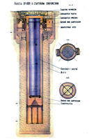
Three new types of silos of a harder configuration began construction in late 1970 at Tyuratam and seven operational ICBM complexes. The walls of all three types are constructed by installing segments formed by heavy metal reinforcing rods attached to an inner steel liner and then fill ing the space between the liner and the silo core with concrete. The headworks are formed from heavy steel components. They all have hinged, plug-type doors that fit flush with the surface. The new small silo (the Type III-G silo) has an internal diameter of 13 to 14 feet, and measurements of silo components lead the US to believe that it had an overall depth of about 100 feet and a usable depth of about 90 feet some five feet deeper than a standard SS-11 silo. Four prototype silos of this type - three of them converted SS-11 silos - were at Tyuratam, and 60 were deployed in groups of 10 at Derazhnya and Pervomaysk, three groups at each complex. These silos in the field were being initially equipped with the SS-11 Mod 3, all of whose test firings over the last two years were from III-G silos. Type III-G silos, however, have also been used for all downrange flight tests of the SS-X-19, making it a candidate to replace these Mod 3s when development is completed. The advanced missile system 15P020U with UR-100U missiles equipped with a MIRV with three warheads of dispersing type (without individual guidance), the development of the TsKBM was the further development of the 15P020 complex. The main task of this complex was to increase its security by creating new silo launchers. The first missile regiment with the UR-100U ICBM and UCP put on combat duty on November 5, 1973 near the town of Pervomaisky (Ukraine). The 15P020U complex with a high-security silo was adopted on September 26, 1974. After the UR-100U missiles were removed from combat duty, the UR-100N missiles were deployed in the upgraded mines, as well as part of the UR-100N UTTC missiles. 60 silos in 1982-1984 were re-equipped under the UR-100N UTTKh ICBM. Later, all the mines of increased security were converted into mines of high security. One group of standard SS-11 silos at Derazhnya and one group at Pervomaysk were converted to a new configuration which used headworks and doors of the type used in III-G silos. It did not appear, however, that the heavy type III-G silo wall segments would be installed and by 1974 it was not clear to US intelligence whether these silos would be deepened. If they were not deepened, the converted silos could accommodate the SS-11 Mod 3, but not the SS-X-19. In one of its SALT I unilateral statements, the United States declared that it would consider any ICBM having a volume significantly greater than that of the largest light ICBM then operational on either side—that is, the SS-11 — to be a heavy ICBM. In 1972 Secretary of Defense Melvin Laird expressed his view during the hearings on SALT agreements that he would interpret this statement such that an increase of more than 30 percent in volume would be significant. The United States considered the issue of agreement to the definition of a heavy ICBM. Its concern stemmed from the fact that the volume of a new Soviet ICBM, the SS-19, is about 50 percent greater than the volume of the currently deployed SS-11, which was defined by the U.S. to be the largest light ICBM operationally deployed by either side at the time of the U.S. unilateral statement of May 26, 1972.. | |||
 |
|||
| Type IIIH | UR-100N / SS-17 | 15P716 | |
|
The technical operation of the 15A16 missile is identical to that of the 15A15 missile. Launcher (15P716) - shaft, automated, highly protected, type "OS" - upgraded PU "OS-84". The conditions for the missile's combat duty are to be in full combat readiness in the silo. The SS-17 was designed for launch from existing SS-11 silos. As thus, the overall dimensions of the SS-17 were determined by the dimensions of the SS-11 UR-100 silos. The diameter of both stages was increased to 2.25 m for the first and 2.1m for the second stage in relative to the previous UR-100. For the MR-UR-100 rocket, one of the first in the USSR was practically realized a "mortar" launch scheme, in which the first-stage DM is launched after the missile is released from the TPK under the pressure of gases produced by special powder gas generators. To provide a mortar launch on the lower part of the rocket, a pallet with a supporting-obturating belt is installed, and on the missile's body - support bands, which are dropped after the missile leaves the TPK. With the mortar launch of the rocket, the gases produced in the powder pressure accumulator enter the volume between the upper and lower bottoms of the pallet. At the time of the start, the mechanical connection between the bottoms is forcibly broken, and under pressuregases acting on the upper bottom of the pallet, the rocket, together with the bottom, is ejected from the TPK. Lower bottom tray with fixed on it PAD remains in the container. | |||
| III-X | Launch Control | ||
|
Three new types of silos of a harder configuration began construction in late 1970 at Tyuratam and seven operational ICBM complexes. The walls of all three types are constructed by installing seg ments formed by heavy metal reinforcing rods attached to an inner steel liner and then fill ing the space between the liner and the silo core with concrete. The headworks are formed from heavy steel components. They all have hinged, plug-type doors that fit flush with the surface. The second type of new large silo (Type III-X) had the same inner diameter as the III-F, 19 to 20 feet. It also narrows to about 16 feet at the top. It differs from the III-F, however, in that it has a circular rather than a rectangular door, appears to be only about 130 feet deep, and has associated construction not present with the III-F. US intelligence believed by 1974 that the III-X silo was intended to house a launch control capsule. In all cases, a single III-X silo had been cbllocated with a group of III-F or III-G silos. The United States was concerned by Soviet deployment of "IIIX" silos with a configuration too similar to a missile-launch silo. The United States was concerned that there are new large silos; that is, III-X silos, under construction in the western USSR, which could be used for launching ICBM's. Though the intelligence community believed that the intended purpose of these new silo-type facilities is for launch control, by 1975 the United States was concerned that these silos may have the capacity to launch ICBMs. By late 1974 it had become apparent that the Russians were telling the truth. This raised a problem, though, for if it was the case that these silos were not for missiles then they ought not to be included in the Soviet ICBM total for SALT. By 1978 the US had accepted the Soviet position that their III–X silos (presumably launch control complexes) are not launchers, precisely on the ground that, although they have all the hardening of launchers and could be converted to launchers by insertion of the appropriate equipment, the US was satisfied that they did not have the necessary equipment to serve as launchers. Ninety-nine launch control facilities (LCFs), referred to as type IIIX silos, had been constructed at deployed ICBM complexes in the Soviet Union by January 1981. These LCFs had been deployed in three different configurations: 15 were for the SS-7 missile, 48 were for theSS-18 missile, and 36 were for the SS-19 missile. An additional ten LCF sites were abandoned in early stages of construction and backfilled. From 1970 until mid-1977, LCFs were deployed in two configurations which were designated as type I and type II LCFs. Neither of these types was deployed after mid-1977. The third configuration, designated as type III, is a significantly modified LCF. The major design variants are a change in the relative position of the launch control support building to the launch control silo and an increase of approximately 2 meters in the usable depth of the silo. At Type I Launch Control Facilities [LCFs], the launch control support building is positioned at a 45-degreeangle to the long axis of the launch control silo apron. There were 35 type I LCFs deployed at both SS-17 and SS-19 launch groups. At Type II LCFs, the launch control support building is positioned perpendicular to and offset from the long axis of the launch control silo apron. There were 19 type II LCFs which were deployed only at SS-18 launch groups. At Type III LCFs, the launch control support building is positioned perpendicular to and in line with the long axis of the launch control silo apron. Forty-five type III LCFs had been identified by 1981 at SS-17, SS-18, and SS-19 launch groups. This included six type I LCFs (three at Derazhnya and three at Pervomaysk) that were modified to type III. This modification program was continuing; activity also indicated that at least some type II LCFs will be modified to type III. | |||
| . | |||
|
NEWSLETTER
|
| Join the GlobalSecurity.org mailing list |
|
|
|

