|
 |
On 12/19/18 6:51 AM, Lars R. wrote:
> I created a special image suitable for uv_mapping on a box and it looks
> fine on a cube.
>
> But when I drill cylindrical holes into the cube the uv_mapping looks
> odd. Moreover it seems that the texture on the holes is also not a
> cylindrical mapping and it does not follow the orientation of the
> cylindrical holes.
>
> See image and scene file.
>
> Is that behavior intentional or is it a bug?
>
> Lars R.
>
>
I'd say results reflect an incomplete implementation/bugs.
---
1) The cylinder uv mapping was not implemented in 3.7 so there you'd be
getting some defaulted behavior (planar?) for the cylinders I guess.
1a) The cylinder mapping was implemented in a fashion with issues for a
while in the master (3.71/now 3.8) branch. If running a 3.8 version
where it was active you'd get a different and probably still incorrect
result for what you are doing. Christoph picked up on issues with how
the mapping was implemented and uv mapping for cylinder, cone and, I
think, lemon were disabled in 3.8 in September. Similar issues exists
for other shapes like the ovus, but there the shapes and mappings
existed in 3.7 (though inverted in y relative to the 3.8 branch) so
those have been left active as in the current 3.8 code.
How (1 / 1a) gets fixed to cleanly define uv_map orientation relative to
the image map is tangled too in how shapes are numerically 'presented'
to the solvers.
2) Part of what you are seeing in your scene as posted - along the
bottom of the cube for example - is related to how the cubic mapping has
been implemented and our image interpolation. The cubic map folds and
where we ask for 'image' interpolation along open edges not mirrored in
incoming images - we get interpolation noise/discontinuities at the open
seams.
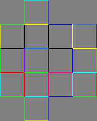
This issue is why I've played on and off with creating cubic image maps
- like that attached - using the user_defined camera. Attempting to get
image interpolation to better work with cubic mapping by creating uv
images with extra image data at the seams. I posted an isosurface wire
box using this sort of interpolation-assist a while back in p.b.i.
In your case you can delete the 'interpolate 3' text to clean up some of
the noise at the bottom of the cube - of course, losing any
interpolation smoothing you wanted everywhere.
Yes, any correct implementation of a box with cylinder holes will
potentially have continuity issues with interpolation on the box /
cylinder map boundaries.
Aside: Your box map won't work smoothly with the cylinder maps even with
cylinderical mapping working. You'll need other map images / scalings
for the cylinders vs box. Not played with uv_map much in CSG, but I
believe the uv mapping gets pushed down to each shape in a set up like
yours. If, for example, you used smaller boxes for cutting into the
larger box it should be the uv_map pigment gets applied correctly
(probably unscaled) to the cut outs. In other words, aside from the
interpolation at open edges bit, things should work as intended in a
difference with all boxes.
Bill P.
Post a reply to this message
Attachments:
Download 'imagemapforcubicinterpolation.png' (4 KB)
Preview of image 'imagemapforcubicinterpolation.png'

|
 |


![]()