
Abstract
This paper is aimed at efficiently distributing workload between the Fog Layer and the Cloud Network and then optimizing resource allocation in cloud networks to ensure better utilization and quick response time of the resources available to the end user. We have employed a Dead-line aware scheme to migrate the data between cloud and Fog networks based on data profiling and then used K-Means clustering and Service-request prediction model to allocate the resources efficiently to all requests. To substantiate our model, we have used iFogSim, which is an extension of the CloudSim simulator. The results clearly show that when an optimized network is used the Quality of Service parameters exhibit better efficiency and output.
1 Introduction
Cloud computing has emerged as an efficient alternative to physical servers and provided benefits such as elasticity and scalability to the end users. Virtualization has allowed dynamic allocation and deallocation of resources in cloud computing data centers and hence a very convenient model based on a pay-as-you-go structure and optimal resource utilization became immensely popular. The growth of cloud popularity and the reliance of various applications on cloud was however unprecedented and no one accurately predicted that a novel paradigm would so quickly become so heavily used. Areas like Body Area Networks, Intra-vehicular communication, smart cities and smart buildings and smart traffic signaling etc. made cloud computing so popular that it is now predicted that the number of end users of the cloud networks would be around four times the Earth's population by year 2050 by [1]. Cloud computing has changed the management of resources and servers for all users, from individuals to organizations. In a cloud environment, we have three service models: IaaS, PaaS, and SaaS, that are used to provide services to the end user over the internet using three deployment models: public clouds, private clouds, and hybrid clouds. Load distribution involves the provisioning of networks, processing power, and resources etc. to complete the user's task. We need load optimization algorithms, which work using machine migration. There are two types of optimization algorithms: static and dynamic, and two machine migration algorithms: sender-initiated and receiver-initiated. There are a few things that must be taken into account while designing an algorithm for optimized workload and allocation. The throughput that determines how many processes have been completed in a single time- unit must be maximized. Response time must be low. Migration time must be as slow as possible. It is the time taken during migration of task from one VM to another to lessen the load of the overloaded Virtual Machine (VM). Performance must be as efficient as possible to get good results. Scalability must be high. Fault tolerance must be high enough so that the algorithm can work efficiently even if there are some errors. Overheads must be low for the algorithm to perform effectively. Resources available must be utilized optimally.
While technology provides some benefits, there are inevitably costs in its use. As cloud networks are spreading widely and are connecting a large number of devices to a large number of servers, there is a certain amount of time it takes to transfer data between them. If that time consumption, is high, it is not feasible in real-time applications. The separation between the storage of huge data and the processing of sensitive data is the only way to deal with the issue. User data that stays on the edge of cloud is transferred to a fog layer, while security and analytical computations are done on the cloud. This model provides a structure containing both cloud and fog. Fog layer devices have ephemeral storage and they are expensive, therefore they cannot be used widely. Thus, we need an optimized workload balancing between fog and cloud layer to achieve high quality of service and increased efficiency.
The research questions that arise when we work to find a solution to the problem at hand are as follows:
Does our architecture effectively represent a distributed environment that is proposed in the paper?
How does the proposed model contribute towards the efficient resource allocation for the coming requests?
How does the proposed model contribute towards the improvement of load optimization?
What qualitative parameters are taken into consideration?
In cloud computing, data centers are far away from the end node, which means there is a possibility of latency, high response time, and increased network usage for the transmission of data. In real-time applications it is imperative that we manage latency and response time to ensure quality of service. In the advent of Internet of Things (IOT) and the evident shortcomings of cloud networks, a new layer of processing, computing and storage was introduced by CISCO in 2014, namely the Fog Layer. The Fog Layer is an extended part of the cloud that enables edge computing and real time applications with the benefits of low latency, mobility, and location accuracy. We find fog computing reliable for real-time data time processing in IoT services and cloud for bulk data analysis. The fog layer is not far from the end node, it can reduce latency, response time and other quality of service parameters like cost, energy, and network usage. Another thing is the increase of nodes with the passage of time.
Fog consists of six layers. Starting from the bottom layer, at the physical layer the edge nodes that contain any type of IoT devices, virtual nodes, sensors, and actuators are distributed geographically and data is collected, normalized, and accumulated from them. At the monitoring layer, the data collected from edge nodes is monitored, as to which type of devices is performing what type of tasks and when and how resources are being used, which are available, and how many are inactive. Energy consumption is also noted from the nodes scattered across the network. At this layer, the collected data is then refined and meaningful information is taken out of it. That data is temporarily stored locally on a temporary storage layer but as soon as it moves to the cloud, it is removed from the storage layer. At the security layer, security measures are taken to keep the data in its form. The integrity of data is ensured by using encryption and decryption techniques. After processing, data is then transported to the cloud via the transport layer and only the data that is required for bulk analysis at the cloud is stored there to reduce storage utilization.
By adding a fog layer, different parameters causing problems in cloud computation can be eliminated, allowing for there can be progress towards more efficient performance of the cloud network. This creates another complication that to overcome, as we need to provide efficient resource utilization and its availability at all times, according to the user's demand. Due to the rapid increase in data, we need to boost load balancing techniques for distribution of the fog and the cloud. For load balancing, we need to evaluate hot data and cold data. Hot data, which is sensitive data, is then transferred to the fog layer for a short period of time and cold data is sent to the cloud for mass storage for longer periods of time. In this paper we have combined K-means clustering and Service-request prediction Model (SRPM) to provide revamped resource allocation. With the help of K-means clustering k clusters are created of n number of virtual machines at the cloud and SRPM keeps the inactive VMs in hibernation mode so as to save energy consumption. The proposed model is concerned about the energy consumption at cloud and to keep the hot data on fog layer that is required to perform real time applications without any delay.
2 Related Work
There are many ways to allocate virtual machines in response to different requests. [2] described CA-LP (Combinatorial Auction-Linear Programming) and CA-GREEDY, which are resource allocation mechanisms. CA-LP performs allocation by linear programming relaxation and randomized rounding. CA-GREEDY employs greedy mechanism and single-minded bidders. There are three types of customers that request resources: demanding customers, least demanding customers, and customers that fall in between. Further demands are also divided based on: the number of requested VMs, valuation, the period of time for which a bundle is requested and deadline. When both mechanisms are compared based on the above divisions of customers and demands, it has been observed that they perform well with fixed pricing. [3] discussed ABRA and also resource utilization is effective as penalty is imposed on unallocated resources. [4] discussed that resource allocation is done by grouping the resources that have the same functionality together and those that have different functionalities are categorized in another group. [5] and [6] compare static and dynamic load balancing algorithms. [7] discussed how to implement resource allocation methods effectively for preemptive tasks but they did not discuss cost and time optimality. [8] discussed how the maximum urgency first algorithm is used to schedule the system, but a critical task can fail in it. [9] proposed a modified round robin algorithm that reduces the overhead by reducing the response time and context switching. [10] also proposed another MRR that provides an improved version of RR algorithm. [11] reflected on dynamic time quantum that changes after every execution of a task. It shows that PBDRR is better than MRR as there is less context switching, average waiting time and average turnaround time.
[12] and [13] gave heuristic algorithms that schedule the tasks on the basis of execution time and system load. In case of dynamic framework, however, this algorithm is unable to predict above mentioned values. [14] gave the weighted round robin cell multiplexing for ATM switch card. [15] discussed how to use deficit round robin for queuing purposes. [16] gave an idea how cloud analytics can be used to solve problems by searching the social networking applications located on the cloud.
In cloud virtualization, a machine is divided into many instances and used by different users at the same time for different purposes. There are two types of virtualization described below. In full virtualization, all the software of one machine is also installed on the other machine. One machine can be used by multiple users. In partial virtualization, different operating systems can be used on a machine and not all services are available to be used; this has been discussed in [17]. Opportunistic load balancing algorithm is a static algorithm in which unexecuted tasks are assigned to the nodes that are available randomly was discussed in [18]. In this way, all the nodes stay busy but processes are completed very slowly. In Min-Min algorithm, at first all the jobs are arranged according to their completion and execution time in a queue. Then the minimum one is selected and assigned to the processors. The assigned task is removed from the queue and it is updated and then again the minimum one is selected as processor is assigned to it. This continues until all the jobs are assigned the processors. In this algorithm, tasks with minimum time will be executed easily but the tasks having large execution time may lead to starvation. In Max-Min algorithm, the jobs are arranged according to their execution time and completion time in queue. Maximum one is selected and processor is assigned to it. In this way, the long jobs do not have to wait longer and no starvation will occur. These steps are followed until the minimum one is also provided the processor but the short jobs have to wait more in this algorithm [19]. The two-phase scheduling load balancing algorithm is the combination of opportunistic load balancing and load balancing min-min. It utilizes the resources effectively and keeps the nodes busy in completing the tasks [20].
In this algorithm, average completion time of tasks is calculated and the average maximum is then selected and assigned to unassigned node with minimum completion time. If all the nodes are assigned already then assigned and unassigned are again evaluated. Minimum completion time of assigned nodes is calculated by the sum the of minimum completion time of all tasks assigned and current task. The sum is thus the minimum completion time of assigned node for current task. This algorithm has no fault tolerance but it utilizes the resources effectively and keeps the nodes busy in completing the tasks.
For cloud computing, heavy systems are required. The big systems require more energy. Energy consumption must be less as it directly affects the cost. A QoS-aware server tries to decrease the energy cost to as low as possible. Service-request prediction model (SRPM) proposed by [21] predicts which VMs of a cluster are inactive. Those will be separated into another cluster thus lowering the energy usage. This model uses service demand data based on time and makes predictions on the future demand data. In k-means clustering [22] cloudlets and VMs are clustered on the basis of some values or properties. This algorithm gives the best results among the other load balancing algorithms.
Dynamic load balancing takes the current situation into account while distributing the load, i.e., there is a table that keeps the info about the current status of node. Workload is distributed on nodes on runtime dynamically. There is master slave concept in it as there is master slave that distributes the tasks among slave nodes. As soon as the load balancer finds out that there is imbalance in the system, it starts to balance the load on all the nodes. The balancer consumes some cycles for monitoring the imbalance situation so we need to handle this as well. In ACCLB (ant colony and complex network theory), ant colony optimization technique is used that finds shortest path between food and ant colony. In dynamic load balancing it is used to distribute the tasks among nodes. A head node is chosen that initializes the work like it is chosen in ant colony to start the movement in a direction. They record the info about the nodes they visit and pheromones are left for other ants to follow them. As soon as the task is done pheromones are updated. The results from each ant are collected to form a single result and if there are some changes, they are made in single result rather than their own results. It improves the system efficiency as the fault tolerance is high but throughput is not high enough. In Honeybee foraging algorithm, there is a group of servers that makes a virtual server and that virtual server has its own process queue. Each virtual server then performs process from their respective queue and finds out its profit. It will return to the forage in case of low profit otherwise stays. This profit calculation may cause overhead, which must be reduced. This technique efficiently balances the load on heterogeneous virtual machines in cloud computing. The current load of VM is calculated so that overloaded and under loaded VMs can be balanced. When a task is being removed from overloaded VM its priority is taken into consideration while assigning it to less loaded VM. [23] argues that using this technique reduces the waiting time of the job and response time of VM.
In Biased Random Sampling load balancing algorithm, the network is represented as a virtual graph. As in a graph, there are vertices; this network has each server as vertex of the node. Each node has an in-degree, which means available resources. Jobs are assigned to the node that has at least one in-degree. As soon as job is assigned, the in-degree will be decremented, and when the job is completed and the resource becomes free, then the in-degree is incremented. Random sampling is used for the deletion and addition of processes. Processes traveling from one node to destination node is called walk length and the maximum walk a process can do to reach its destination node is called threshold value. The neighboring node is selected for traversal. The load balancer selects a node randomly as soon as request is received and compares current nodes walk length with the threshold value. If walk length is greater than or and equal to the threshold value, then the process will be executed on that node, otherwise another node is selected randomly. The performance of the algorithm decreases with the increase in servers because of more overhead. In [24] weighted round robin VMs are assigned weights and they do not take jobs more than their weights so that VMs are neither overloaded neither less loaded. In Throttled algorithm, the best suitable VM is searched and then it is assigned that task. In [25], efficient throttled algorithm hash map is used for efficient searching of suitable virtual machine. DCBT algorithm uses divide and conquer and throttled algorithm for load optimization. In dynamic load management algorithm, there is a table managing the VMs available or not available. The available VMs are assigned tasks and busy ones are added to a separate group and are added back to available VMs group when task is completed.
In [26], genetic algorithm assigns binary values to possible solutions and then they are mutated to produce the one. The disadvantage is that the selection of best pair is not taken into account rather random pair is used [27]. In improved genetic algorithm, tournament selection method is used to find out the best pair to get the best solution out of it [28]. In [29], novel honey bee inspired algorithm has parameters for checking the quality and then chooses the best optimal resource. Stochastic hill climbing algorithm assigns jobs to VMs in a loop and increases value until the value is highest in [30]. In [31], ant colony optimization algorithm master slave architecture is used. Master node is provided the task that sub divides it and distributes it among slave nodes and then gather results from them when task is completed and combine the result. Particle swarm algorithm transfers the VM instead of transferring the workload [32]. In [33], LB-BC algorithm clusters of hosts are made upon taking into account the CPU resource, memory, and previous probability. The tasks are assigned according to the cluster capability. Cluster based load optimization makes clusters of network. Each cluster has master and slave nodes. Master slave distributes tasks among slave nodes in cluster. In [34], Round robin algorithm is used for load distribution.
However, in none of the related work a technique for optimal resource allocation and workload balancing for fog enabled IoT has been presented. In light of the literature that we studied we reached the conclusion that in order to achieve a solution to our problem statement, the most appropriate way forward would be to employ K-mean clustering on the data center resources and combine the VMs with similar characteristics and then using SRPM on each cluster that hibernates the inactive VMs to reduce the energy consumption. Our goal is to balance load between cloud and fog environments by identifying hot and cold data based on input/output per second and then optimize resource allocation in cloud networks by making clusters of virtual machines based on their characteristics and then within those clusters to create and hibernate idle VMs to reduce resource consumption. We will finally evaluate the benefits of our work by seeing improvement in Quality of service (QoS) parameters brought about by our research. Many services that the cloud computing paradigm renders have real time processing involved. As IoT becomes more popular and cloud usage increases the cloud network is bound to become congested. This can cause problems like jitter and delay, which in many cases could be harmful or even fatal to the end user. For instance, in health care services or traffic signaling, delay of seconds can be catastrophic. The prevention of such delays is our main motivation for workload balancing optimization between fog and cloud networks.
3 Proposed Methodology
In our proposed methodology we have two phases. The first is to balance the load between fog networks and cloud networks and the second is to perform resource allocation among virtual machines in the cloud effectively. When a user sends data to a cloud network, the effectiveness of the processed results depends on the nature of the application with exponential increase in IoT applications. The traditional cloud network is becoming congested and problems like jitter and delay are bound to arise. These problems are critical to real-time applications especially when real-time results are time critical. It was therefore necessary to introduce an intermediate layer between the user and cloud network called the fog layer. Our first step is to balance the load between the fog layer and the cloud layer based on parameters such as type of data, data temperature and migration deadline. The second phase deals with the optimization of cloud resource allocation for analytical and bulk data. Here the intent is to make clusters of appropriate VMs to save energy of virtual machines that are not required at that time and maximize the resource consumption by optimally allocating VMs to active cluster of servers. The complete process of the proposed methodology is shown in Figure 2.
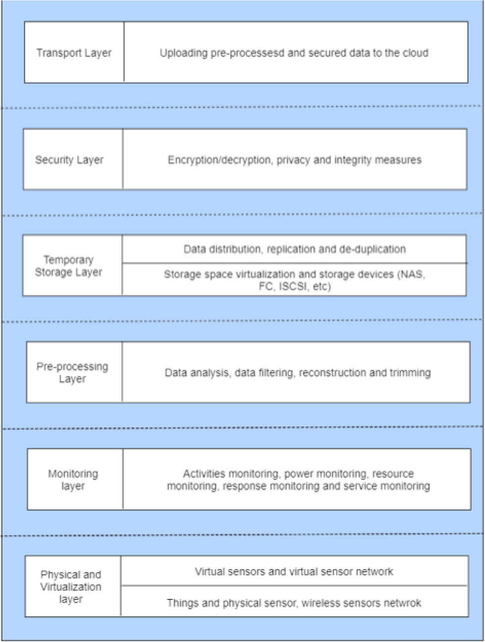
Layered architecture of fog computing
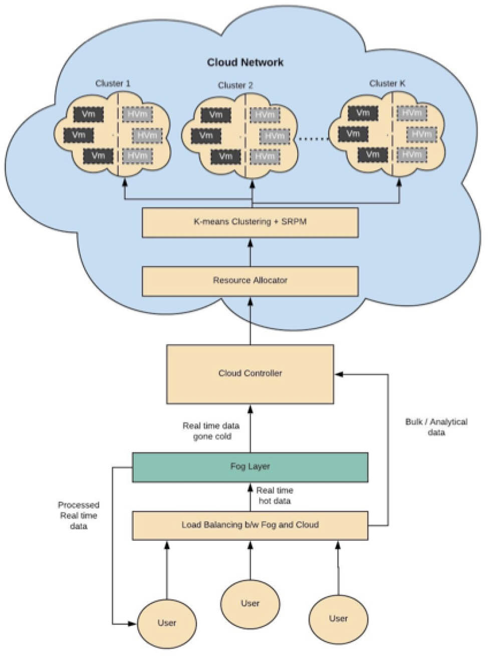
Proposed Model for Optimized Load Balancing and Resource Allocation in Fog enabled IoT
To benefit fully from the concept of Fog computing, we have to devise a framework that would ensure a systematic extension of a Cloud environment to an environment that showcases a Cloud and a Fog layer. We have identified four major parts of the migration process: Data shift, Application shift, Service shift, and Security measures. Data shift of the migration process begins with the identification of different end-node devices as Fog storage devices. Routers, sensors, terminals, and other devices that interact with the cloud can be used in a localized network to form a layer between the end user and the cloud network. This layer is called the fog layer. The process of shifting data from these fog devices to the cloud network and vice versa requires differentiation of data on the basis of its “hotness”. Data is considered hot when it is required for real-time processing and requires a substantial number of Inputs and Outputs per second (IOPS). Application shift will take care of deploying distributed applications at the client and server ends with one part of the application handling the real-time processing on the Fog device and the other part handling bulk processing and storage on the cloud device. Both these parts would have to be integrated and synchronized to ensure both accuracy of real-time results and maintenance of integrity of bulk data stored at the cloud end. It is imperative that some sort of mechanism is devised that would determine the workload sharing of the real-time and the bulk module of the application. Service shift of the migration framework would provide service architecture models for IaaS, PaaS, and SaaS. A separate paper proposing these models for Fog computing is in the publication process. One of these models is used later in this paper. Security measures have been the most talked about area of research in cloud computing. The public cloud has faced severe criticism because of its fragile security. Fog computing provides a solution by providing some sort of control over the distribution and proximity of critical data. It is, however, necessary to employ techniques like PKI and CA to actually make the Fog networks a more secure alternative to cloud computing.
This paper discusses the first part of the migration framework, which addresses data migration between Cloud and Fog. This data migration would include a determination of the kind of storage devices that would be available at the Fog layer and their comparison with the Cloud storage devices. An additional concern will be some sort of mechanism that can differentiate data on the basis of latency sensitivity and data temperature. Finally, an Infrastructure-as-a-service model for Fog computing would be used to help demonstrate how movement of data would take place between Clouds and Fog. In our work we are concerned primarily with Data Migration as explained in the following subsections.
3.1 Data Profiling
To migrate the right amount and kind of data from Cloud to Fog and vice versa we need to differentiate data according to some parameters. In case of Fog computing the main concern with regards to access and processing of data is latency. This means that one parameter that must be considered when deciding what data to move to the Fog layer would be latency sensitivity. Another aspect of data that needs consideration in this regard is its temperature.
3.2 Data Temperature
Data can be deemed “hot” or “cold” depending on its usage. “Hot” data would typically be data that is to be processed within a given time frame. As the time passes this “hot” data becomes less critical and hence its temperature is said to have cooled down resulting in the term “cold” data. At a particular instance, the determination of “hot-spots” in the stored data can be done by IO profiling whereby IOPS-intensive data is shifted to the faster Fog layer. In this regard a key challenge arises from the fact that hot-spots in data continue to move over time, i.e., previously cold data that is seldom accessed would suddenly or gradually become hot due to it being frequently accessed or becoming performance critical in response to a certain event. Such fluctuations in the nature of data require us to devise an adaptive mechanism that can assess the future needs of the system and migrate appropriate chunks of data from Cloud to Fog and vice versa. Deadline Data selection for migration requires preemptive determination of hot or latency-sensitive data. Such determination requires screening data for certain indications such as criticality and IOPS-sensitivity. One major aspect of this screening is the determination of a reasonable deadline within which the migration has to be completed in order to meet the deadline of the workload to which the “hot” data is associated.
Let “t” be the response time during time period [t1,t2]. The response time function for a multi-tiered Fog environment can then be denoted as,
The conventional unit of response time is milliseconds. Figure 3 shows three phases of data migration between end user, fog and cloud networks. In the first phase of the migration model, it continuously observes the I/O profile and sorts the extent list by its temperature. If this phase takes x time, then utility would be
The second phase deals with data migration. A very limited chunk of data is hot, so every chunk adds load thereby reducing the response time. After certain chunks’ migration, further reduction in response time is not possible. This point is called convergence and it calculates the average response time.
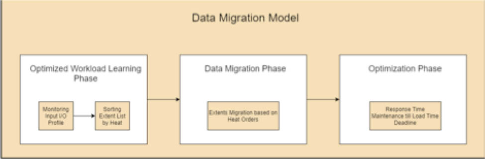
Data Migration Model
If y time is taken by the migration phase, then utility cost would be
After the phase reaches the convergence point, the optimization phase starts. In this phase response time is kept average until the deadline. Thus, if optimization takes z time the utility would be
The total workload cycle would be sum of time taken by all the three phases
One migration of data from fog to cloud or vice versa would be
When given peak response time (p) and saturation time (u), the data migration response time function would be
In case of single data migration, the response time function would be,
Thus from above equations the utility cost for one migration would be
For reduced utility cost and faster response time it is important to calculate utility rise i.e.
At this point it is clear now that the utility cost differential improves data migration between fog and cloud and to implement it we need a framework.
3.3 Data Migration between Cloud and Fog
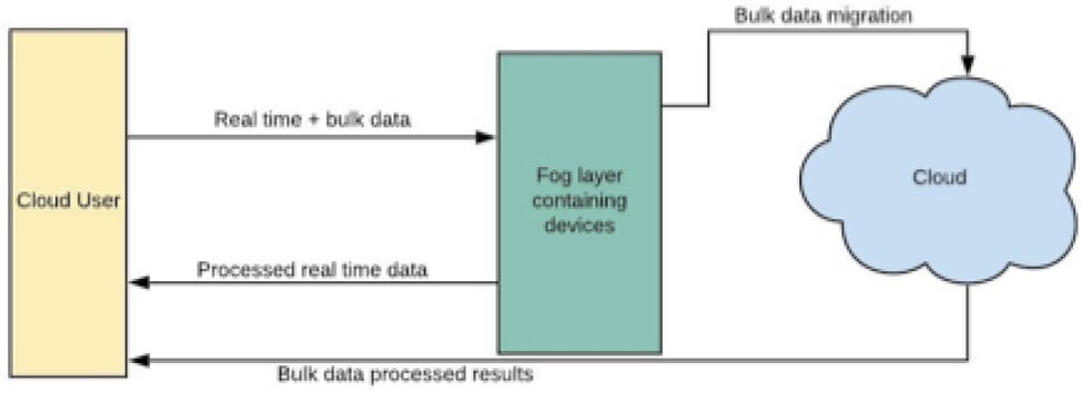
Fog computing in IaaS infrastructure provides distributed framework that performs real-time processing and storage for fog and bulk data processing and storage on cloud separately. This is represented in Figure 4.
IaaS for Fog
In IoT applications, two types of storage are required to use the fog services. In Figure 4 there is a fog layer that deals with the temporary storage and fast processing of data, while the cloud layer provides a large amount of permanent storage of data that can help in creating analytical reports. By combining ADAS [35] and the above proposed infrastructure utility cost and response can be reduced that leads to reduction in latency while migrating data between cloud and fog.
3.4 Resource Allocation for Cloud Networks
Following are the steps involved in the resource allocation for cloud networks in our proposed model.
Step 1: VMs are initially specified by their resource type, capacities, and status. There are two types of virtual machines discussed below. In system virtual machine, a physical machine is divided into different VMs. Each VM act as a single computer and not interlinked with any other VMs. Each can therefore have a different operating system. Process virtual machine is useful for a programmer to run his application on a VM with installed operating system of organization and its standers of computers. A programmer can run its application regardless of the platform. Following are the various VM statuses.
Provisioning
Provisioning error
Customizing
Delete
Waiting for agent
Startup
Agent unreachable
Configuration error
Provisioned
Available
Checked out
Connected
Disconnected
Unassigned user connected
Unassigned user disconnected
Unknown
Maintenance mode and Error
Step 2: K clusters are created of n VMs. Clustering is done by K-Means clustering depending on values like client's priority, cost of cloudlet, and instruction width of cloudlet. In K Means Clustering, K is defined earlier. VM that matches a particular cluster is added into it. If undesirable result shows up, k clustering is implemented again and it continues until no VM is left behind.
Step 3: Each type of cluster acts as a server. K clusters create k servers. Each server contains the VMs closest to each other. So whichever request matches the cluster, a VM from that cluster is assigned to it.
Step 4: After certain time, the resource allocator checks if there are VMs of a server that continued to stay inactive If so, they will be grouped together and will hibernate. This is done by using Service-request prediction model. It predicts which VMs of a cluster are inactive. Those will be separated into another cluster thus lowering the energy usage. This model uses service demand data based on time and makes predictions on the future demand data.
Step 5: If that server needs more VMs later to complete a request and not be overloaded,. Inactive VMs can be added back depending on the number of VMs required for the task.
Step 6: As soon as a new request reaches the cloud controller, request is directed to the resource allocator.
Step 7: The resource allocator finds the best suited cluster for the request and assigns VM from that cluster to the request that is available.
Step 8: List is updated about available VMs in that cluster.
Step 9: When request is done using VM, list is updated again.
Step 10: For every new request go back to step 7.
After the use of K-mean clustering to identify suitable VMs, Service request prediction model (SRPM) can help to deal with the efficient management of VMs while consuming the energy optimally. In SRPM the VMs that are not providing any services to any upcoming request and are inactive for a long time are identified and put into sleeping mode hence they hibernate until the VMs that are active are overloaded. As soon as active VMs are overloaded and there are VMs that are hibernating, they become active and act as resources for the upcoming requests. Figure 5 shows the above-mentioned resource allocation.
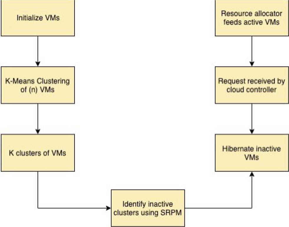
Resource allocation using K-mean clustering and SRPM
4 Application of the Proposed Methodology
In this section we demonstrate the application of our proposed methodology using real-time patients’ care for provision of first aid. There are four main modules in this case study: Timer Module needs to inform checker module in time about the severe condition of patient, Checker Module checks which particular group of patients he belongs to, Potency Calculator Module determines the dosage of medicine required for such group of patients, and Selector module selects single patient to inject the dosage by the help of actuator injector. Interface module receives data from timer module. In interface it is evaluated if some information is missing or any error occurred and then results are generated after all these calculations to inform checker module about the situation. Cloud storage is informed by the actuator injector. This is helpful in keeping patient's reports and the analysis about the previous and current situation of patient. It also provides the interface for the physician to take a look at patient's reports when required. The complete process is shown in Figure 6.
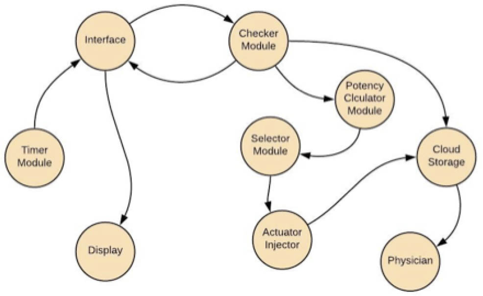
Application Model of Patient-Medicine Administration
The simulator that we have used for our case study is ifogsim, which is an extension for cloudsim simulator. It can model applications based on geographical proximity by making geo coverage maps. Ifogsim also has the ability to evaluate the quality of service parameters related to fog and cloud simulations. These parameters include cost, energy consumption, efficiency etc. Following are the steps involved in the execution of our simulation. Since ifogsim is based on cloudsim it uses cloudsim as its primary engine in order to perform many tasks such as data center creation, which is the core part of isimualtion process. In step 1 we initialize cloudsim by assigning certain parameters. The number of users for the desired simulation is set to 1. The calendar is initialized to keep the current instance until the time when the simulation commences. Finally, we initialize the trace-flag as false in order to hide the details log irrelevant to the current simulation. In step 2 a fog broker is initialized based on the data-center broker. The purpose of data-center broker is to create coordination between cloud-service-providers and end-users on the basis of needs related to quality-of-service (QoS) requirements. A fog broker operates on the fog layer and assists the end users in creating tuples. Tuples are taken from the cloudlets class in cloudsim, which is used to present tasks in cloudsim. In the same way tuples class models tasks for fog environments in various modules in ifogsim. In step 3 cloud-data-centers and fog-data-centers are created with the below mentioned properties. The properties for both cloud-data-centers and fog-data-centers vary because of the nature of the networks. Trying to emulate reality we set the properties of our fog devices so that they are less powerful than our cloud-processing-devices and their storage capacities are smaller than the capacity of the cloud-data-center. The properties of our appropriate cloud devices are shown in Table 1. Table 2 shows the properties of our fog devices, which are less powerful but much closer to the source of data generation.
Cloud data Center Characteristics
| Name of Device | Cloud |
|---|---|
| Million instructions per second | 44880 |
| RAM | 40G |
| Uploading Bandwidth | 100 Mbits/sec |
| Downloading Bandwidth | 10 Gbits/sec |
| Parent Level | 0 (top of the topology) |
| Rate per processing usage | 0.01 |
| Busy Power | 1648 W |
| Idle Power | 1332 W |
Fog Data Center Characteristics
| Name of Device | Proxy Server |
|---|---|
| Million instructions per second | 2800 mips |
| RAM | 4 G |
| Uploading Bandwidth | 10 Gbits/sec |
| Downloading Bandwidth | 10 Gbits/sec |
| Parent Level | 1 (Child of cloud) |
| Rate per processing usage | 0.01 |
| Busy Power | 102 W |
| Idle Power | 80 W |
| Latency between cloud and proxy server | 100 ms |
4.1 Gateway Devices
These devices generate a communication pathway between fog and cloud devices. These devices are installed at the 2nd last position in the model. Table 3 shows the properties of gateway devices.
Gateway Device Characteristics
| Million instructions per second | 2800 mips |
| RAM | 4 G |
| Uploading Bandwidth | 10 Gbits/sec |
| Downloading Bandwidth | 10 Gbits/sec |
| Level | 2 (Below proxy server) |
| Busy Power | 102 W |
| Idle Power | 79 W |
| Latency between gateway and proxy server | 4 ms |
4.1.1 Observer Devices
There are some observer devices in our model that are end nodes of the network. Table 4 shows the characteristics of the observer devices.
Observer Device Characteristics
| Million instructions per second | 1000 mips |
| RAM | 1 Gb |
| Uploading Bandwidth | 10 Gbits/sec |
| Downloading Bandwidth | 270 Gbits/sec |
| Level | 3 (Below gateways) |
| Busy Power | 85 W |
4.2 Sensors and Actuators
In above case study there are some sensors and actuators to perform the tasks as a result of certain conditions for IoT based devices. Sensor senses how and which individual needs to be taken care of in severe condition and how actuators perform the tasks.
4.3 Module to Module Interaction
Communication is done within the devices via interaction between modules. A set of instructions in the form of tuple is sent and received to module to perform communication. The instruction set in the form of tuples are sent to the cloud or fog are called TuplesUp and the tuples sent between modules are known as TuplesDown. In ifogSim tuplemapping is used to map tuples to modules.
4.4 Network Topology for Simulation in ifogsim
Our topology consists of a traditional cloud network linked to multiple fog areas through a proxy server. Figure 7 shows two areas, however we have generated results on three areas. Each area contains two Line protection units (LPUs) which connect the fog to end user devices.
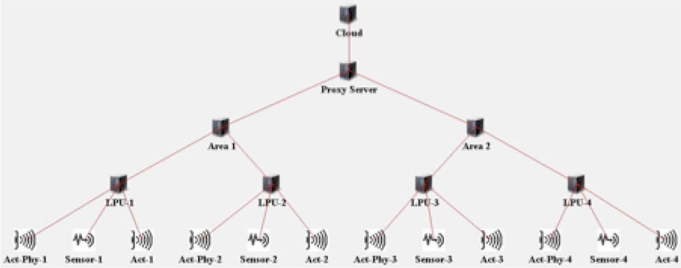
Network topology for ifogsim
5 Results
Results of the simulation discussed above are given below.
5.1 Latency
Average latency and energy consumption is calculated by taking all values from one module to other. Table 5 shows that there is a reduction in latency when fog architecture is utilized.
Latency in Cloud and Fog Architecture
| Configuration | Number of Areas | Number of LPU | Cloud | Fog |
|---|---|---|---|---|
| 1 | 1 | 2 | 225 | 16 |
| 2 | 2 | 4 | 227 | 20 |
| 3 | 3 | 6 | 2694 | 34 |
5.2 Execution Cost
Different parameters are taken into account to calculate the operational cost. In this table latency and energy consumption is higher if there is no fog and no hibernation of VMs. As we can see in the table, fog with hibernation gives less cost. Table 6 shows that there is a reduction in execution cost when fog architecture is utilized.
Execution Cost with cloud and fog architecture
| Configuration | Number of Areas | Number of LPU | Cloud | Fog |
|---|---|---|---|---|
| 1 | 1 | 2 | 293384 | 9456 |
| 2 | 2 | 4 | 3946184 | 25567 |
| 3 | 3 | 6 | 4197088 | 52419 |
5.3 Network Usage
Network usage gives information about total utilization in kilobytes. Results are shown below; more devices lead to more network consumption. In fog with hibernation of virtual machines it is evident that it uses less network than no hibernating virtual machine in the absence of fog. Table 7 shows that network usage is reduced when fog architecture is utilized.
Network Usage with cloud and fog architecture
| Configuration | Number of Areas | Number of LPU | Cloud | Fog |
|---|---|---|---|---|
| 1 | 1 | 2 | 59530 | 7007 |
| 2 | 2 | 4 | 257710 | 31814 |
| 3 | 3 | 6 | 598010 | 87100 |
5.4 Energy Consumption
Below given table is showing the energy consumption between fog with hibernating virtual machines and no hibernating virtual machine in the absence of fog. Table 8 shows that there is a persistent usage of energy when fog architecture is utilized.
Energy consumed with cloud and fog architecture
| Configuration | Number of Areas | Number of LPU | Cloud | Fog |
|---|---|---|---|---|
| 1 | 1 | 2 | 1.3 | 1.3 |
| 2 | 2 | 4 | 1.6 | 1.3 |
| 3 | 3 | 6 | 1.8 | 1.3 |
5.5 Execution Time
Execution time represents the total time it takes by edge node devices to execute requests. It calculates the cumulative time for transporting sensors, data and processing and conveying results. We test fog and cloud with the same amount of workload. There is a considerable reduction in execution time for fog networks as compared to cloud networks. This is because fog nodes are placed nearer to the users then cloud networks as shown in Table 9.
Execution time with cloud and fog architecture
| Configuration | Number of Areas | Number of LPU | Cloud | Fog |
|---|---|---|---|---|
| 1 | 1 | 2 | 1097 | 800 |
| 2 | 2 | 4 | 4802 | 3126 |
| 3 | 3 | 6 | 9203 | 6632 |
6 Discussion and Conclusion
In light of the results presented in the previous section we can safely determine that fog networks provide greater efficiency over traditional cloud networks especially when efforts are made to distribute load in an appropriate manner between the fog and cloud networks. We have also established that optimized resource allocation within cloud networks once coupled with workload balancing has immense potential to improve quality of service parameters such as latency, network delays, geographical distribution, execution cost, and energy consumption etc. The model presented in this paper is molded to accommodate a system based on low latency and quick response in real time situations. The workload balancing mechanism presented in the dissertation segregates data into two parts based on the number of instructions that access the data. One of the issues related to cloud computing has been the mandatory use of private clouds to ensure a less latent and more secure use of technology. This makes the use of fixed resources and fixed costs compulsory and hence the true advantages of cloud computing are reaped. In our presented models the complete hierarchy of the business process from creating and storing to deploying applications is carried out simply through rented resources provided by the highly distributed fog environment. The close proximity of the real time processing unit makes sure that the users have greater control on data and data is highly secure. This leaves no reason to use a private cloud; based on our work load balancing technique the software developer will create two modules of his application, one for the cloud network and the other for the fog network. This can be done by using a platform-as-a-service at the Fog node level using IOX, which is the main development platform over Fog.
At the cloud level we have employed resource allocation by clustering and profiling of virtual machines and that optimizes the use of VMs and makes the utilization of resources most appropriate.
Overall the contribution of this paper goes a long way in making the use of workload balancing and resource allocation for optimization of Quality of Service parameters in IOT enabled Fog.
References
[1] Clohessy T., Acton T., Morgan L., Smart city as a service (SCaaS): A future roadmap for e-government smart city cloud computing initiatives, Proceedings of the 7th IEEE/ACM International Conference on Utility and Cloud Computing, 2014, 836–84110.1109/UCC.2014.136Search in Google Scholar
[2] Zaman S., Grosu D., Combinatorial auction-based allocation of virtual machine instances in clouds, Journal of Parallel and Distributed Computing, 2013, 73(4), 495–50810.1109/CloudCom.2010.28Search in Google Scholar
[3] Özer A. H., Özturan C., An auction based mathematical model and heuristics for resource co-allocation problem in grids and clouds, Proceedings of the Fifth IEEE International Conference on Soft Computing, Computing with Words and Perceptions in System Analysis, Decision and Control, 2009, 1–4.10.1109/ICSCCW.2009.5379493Search in Google Scholar
[4] Zhang Y., Niyato D., Wang P., An auction mechanism for resource allocation in mobile cloud computing systems, Proceedings of International Conference on Wireless Algorithms, Systems, and Applications, Springer, Berlin, Heidelberg, 2013, 76–87.10.1007/978-3-642-39701-1_7Search in Google Scholar
[5] Randles M., Lamb D., Taleb-Bendiab A., A comparative study into distributed load balancing algorithms for cloud computing, Proceedings of 24th IEEE International Conference on Advanced Information Networking and Applications Workshops, 2010, 551–55610.1109/WAINA.2010.85Search in Google Scholar
[6] Alakeel A. M., A guide to dynamic load balancing in distributed computer systems, International Journal of Computer Science and Information Security, 2010, 10(6), 153–60Search in Google Scholar
[7] Li J., Qiu M., Niu J. W., Chen Y., Ming Z., Adaptive resource allocation for preemptable jobs in cloud systems, Proceedings of 10th IEEE International Conference on Intelligent Systems Design and Applications, 2010, 31–3610.1109/ISDA.2010.5687294Search in Google Scholar
[8] Stewart D. B., Khosla P. K., Real-time scheduling of dynamically reconfigurable systems, Proceedings of IEEE International Conference on Systems Engineering, 1991, 139–14210.1109/ICSYSE.1991.161098Search in Google Scholar
[9] Singh A., Goyal P., Batra S., An optimized round robin scheduling algorithm for CPU scheduling, International Journal on Computer Science and Engineering, 2010, 2(7), 2383–2385Search in Google Scholar
[10] Yaashuwanth C., Ramesh R., Design of Real Time Scheduler Simulator and Development of Modified Round Robin Architecture for Real Time System, International Journal of Computer and Electrical Engineering, 2010, 10(3), 43–47Search in Google Scholar
[11] Mohanty R., Behera H. S., Patwari K., Dash M., Prasanna M. L., Priority based dynamic round robin (PBDRR) algorithm with intelligent time slice for soft real time systems, arXiv preprint, 2011, arXiv:1105.173610.14569/IJACSA.2011.020209Search in Google Scholar
[12] Casanova H., Legrand A., Zagorodnov D., Berman F., Heuristics for scheduling parameter sweep applications in grid environments, Proceedings of IEEE 9th Heterogeneous Computing Workshop (HCW 2000), 2000, 349–363.Search in Google Scholar
[13] Baraglia R., Ferrini R., Ritrovato P., A static mapping heuristics to map parallel applications to heterogeneous computing systems, Concurrency and Computation: Practice and Experience, 2005, 17(13), 1579–160510.1002/cpe.902Search in Google Scholar
[14] Katevenis M., Sidiropoulos S., Courcoubetis C., Weighted round-robin cell multiplexing in a general-purpose ATM switch chip, IEEE Journal on selected Areas in Communications, 1991, 9(8), 1265–127910.1109/49.105173Search in Google Scholar
[15] Shreedhar M., Varghese G., Efficient fair queuing using deficit round-robin, IEEE/ACM Transactions on networking, 1996, 4(3), 375–38510.1109/90.502236Search in Google Scholar
[16] Wickremasinghe B., Calheiros R. N., Buyya R., Cloudanalyst: A cloudsim-based visual modeller for analysing cloud computing environments and applications, Proceedings of 24th IEEE international conference on advanced information networking and applications, 2010, 446–45210.1109/AINA.2010.32Search in Google Scholar
[17] Mishra R., Jaiswal A., Ant colony optimization: A solution of load balancing in cloud, International Journal of Web & Semantic Technology, 2012, 3(2), 3310.5121/ijwest.2012.3203Search in Google Scholar
[18] Hung C. L., Wang H. H., Hu Y. C., Efficient load balancing algorithm for cloud computing network, Proceedings of International Conference on Information Science and Technology, 2012, 28–30Search in Google Scholar
[19] Kokilavani T., Amalarethinam D. G., Load balanced min-min algorithm for static meta-task scheduling in grid computing, International Journal of Computer Applications, 2011, 20(2), 43–4910.5120/2403-3197Search in Google Scholar
[20] Kaur K., Narang A., Kaur K., Load balancing techniques of cloud computing, International Journal of Mathematics and Computer Research, 2013, 1(3), 103–110Search in Google Scholar
[21] Mohan N. R., Raj E. B., Resource Allocation Techniques in Cloud Computing–Research Challenges for Applications, Proceedings of fourth international conference on computational intelligence and communication networks, 2012, 556–56010.1109/CICN.2012.177Search in Google Scholar
[22] Adrian B., Heryawan L., Analysis of K-means algorithm for VM allocation in cloud computing, Proceedings of International Conference on Data and Software Engineering (ICoDSE), 2015, 48–5310.1109/ICODSE.2015.7436970Search in Google Scholar
[23] LD D. B., Krishna P. V., Honey bee behavior inspired load balancing of tasks in cloud computing environments, Applied soft computing, 2013, 13(5), 2292–230310.1016/j.asoc.2013.01.025Search in Google Scholar
[24] Megharaj G., Mohan K. G., A survey on load balancing techniques in cloud computing, IOSR Journal of Computer Engineering (IOSRJCE), 2016, 18(2), 55–61Search in Google Scholar
[25] Domanal S. G., Reddy G. R., Load balancing in cloud environment using a novel hybrid scheduling algorithm, Proceedings of IEEE International Conference on Cloud Computing in Emerging Markets (CCEM), 2015, 37–4210.1109/CCEM.2015.31Search in Google Scholar
[26] Panwar R., Mallick B., Load balancing in cloud computing using dynamic load management algorithm, Proceedings of International Conference on Green Computing and Internet of Things (ICGCIoT), 2015, 773–77810.1109/ICGCIoT.2015.7380567Search in Google Scholar
[27] Dasgupta K., Mandal B., Dutta P., Mandal J. K., Dam S., A genetic algorithm (ga) based load balancing strategy for cloud computing, Procedia Technology, 2013, 10, 340–34710.1016/j.protcy.2013.12.369Search in Google Scholar
[28] Patel R. R., Patel S. J., Patel D. S., Desai T. T., Improved GA using population reduction for load balancing in cloud computing, Proceedings of International Conference on Advances in Computing, Communications and Informatics (ICACCI), 2016, 2372–237410.1109/ICACCI.2016.7732410Search in Google Scholar
[29] Korat C., Gohel P., A novel honey bee inspired algorithm for dynamic load balancing in cloud environment, International Journal of Advanced Research in Electrical, Electronics and Instrumentation Engineering, 2015, 4.10.15662/ijareeie.2015.0408025Search in Google Scholar
[30] Mondal B., Dasgupta K., Dutta P., Load balancing in cloud computing using stochastic hill climbing-a soft computing approach, Procedia Technology, 2012, 4, 783–78910.1016/j.protcy.2012.05.128Search in Google Scholar
[31] Gao R., Wu J., Dynamic load balancing strategy for cloud computing with ant colony optimization, Future Internet, 2015, 7(4), 465–48310.3390/fi7040465Search in Google Scholar
[32] Ramezani F., Lu J., Hussain F. K., Task-based system load balancing in cloud computing using particle swarm optimization, International journal of parallel programming, 2014, 42(5), 739–75410.1007/s10766-013-0275-4Search in Google Scholar
[33] Zhao J., Yang K., Wei X., Ding Y., Hu L., Xu G., A heuristic clustering-based task deployment approach for load balancing using Bayes theorem in cloud environment, IEEE Transactions on Parallel and Distributed Systems, 2015, 27(2), 305–316.10.1109/TPDS.2015.2402655Search in Google Scholar
[34] Dhurandher S. K., Obaidat M. S., Woungang I., Agarwal P., Gupta A., Gupta P., A cluster-based load balancing algorithm in cloud computing, Proceedings of IEEE International Conference on Communications (ICC), 2014, 2921–292510.1109/ICC.2014.6883768Search in Google Scholar
[35] Khalid A., Shahbaz M., Adaptive Deadline-aware Scheme (ADAS) for Data Migration between Cloud and Fog Layers, KSII Transactions on Internet & Information Systems, 2018, 12(3), 1002–101510.3837/tiis.2018.03.001Search in Google Scholar
© 2021 Adnan Khalid et al., published by De Gruyter
This work is licensed under the Creative Commons Attribution 4.0 International License.