Category Archives: Mandelbulb

Path Tracing 3D Fractals

In some ways path tracing is one of the simplest and most intuitive ways to do ray tracing.

Imagine you want to simulate how the photons from one or more light sources bounce around a scene before reaching a camera. Each time a photon hits a surface, we choose a new randomly reflected direction and continue, adjusting the intensity according to how likely the chosen reflection is. Though this approach works, only a very tiny fraction of paths would terminate at the camera.

So instead, we might start from the camera and trace the ray from here and until we hit a light source. And, if the light source is large and slowly varying (for instance when using Image Based Lighting), this may provide good results.

But if the light source is small, e.g. like the sun, we have the same problem: the chance that we hit a light source using a path of random reflections is very low, and our image will be very noisy and slowly converging. There are ways around this: one way is to trace rays starting from both the camera and the lights, and connect them (bidirectional path tracing), another is to test for possible direct lighting at each surface intersection (this is sometimes called ‘next event estimation’).

Even though the concept of path tracing might be simple, introductions to path tracing often get very mathematical. This blog post is an attempt to introduce path tracing as an operational tool without going through too many formal definitions. The examples are built around Fragmentarium (and thus GLSL) snippets, but the discussion should be quite general.

Let us start by considering how light behaves when hitting a very simple material: a perfect diffuse material.

Diffuse reflections

A Lambertian material is an ideal diffuse material, which has the same radiance when viewed from any angle.
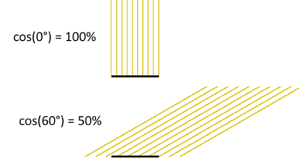
Imagine that a Lambertian surface is hit by a light source. Consider the image above, showing some photons hitting a patch of a surface. By pure geometrical reasoning, we can see that the amount of light that hits this patch of the surface will be proportional to the cosine of the angle between the surface normal and the light ray:

\(
cos(\theta)=\vec{n} \cdot \vec{l}
\)
 
By definition of a Lambertian material this amount of incoming light will then be reflected with the same probability in all directions.

Now, to find the total light intensity in a given (outgoing) direction, we need to integrate over all possible incoming directions in the hemisphere:

\(
L_{out}(\vec\omega_o) = \int K*L_{in}(\vec\omega_i)cos(\theta)d\vec\omega_i
\)
 
where K is a constant that determines how much of the incoming light is absorbed in the material, and how much is reflected. Notice, that there must be an upper bound to the value of K – too high a value would mean we emitted more light than we received. This is referred to as the ‘conservation of energy’ constraint, which puts the following bound on K:

\(
\int Kcos(\theta)d\vec\omega_i \leq 1
\)
 
Since K is a constant, this integral is easy to solve (see e.g. equation 30 here):

\(
K \leq 1/\pi
\)
 
Instead of using the constant K, when talking about a diffuse materials reflectivity, it is common to use the Albedo, defined as \( Albedo = K\pi \). The Albedo is thus always between 0 and 1 for a physical diffuse materials. Using the Albedo definition, we have:

\(
L_{out}(\vec\omega_o) = \int (Albedo/\pi)*L_{in}(\vec\omega_i)cos(\theta)d\vec\omega_i
\)
 
The above is the Rendering Equation for a diffuse material. It describes how light scatters at a single point. Our diffuse material is a special case of the more general formula:

\(
L_{out}(\vec\omega_o) = \int BRDF(\vec\omega_i,\vec\omega_o)*L_{in}(\vec\omega_i)cos(\theta)d\vec\omega_i
\)
 
Where the BRDF (Bidirectional Reflectance Distribution Function) is a function that describes the reflection properties of the given material: i.e. do we have a shiny, metallic surface or a diffuse material.
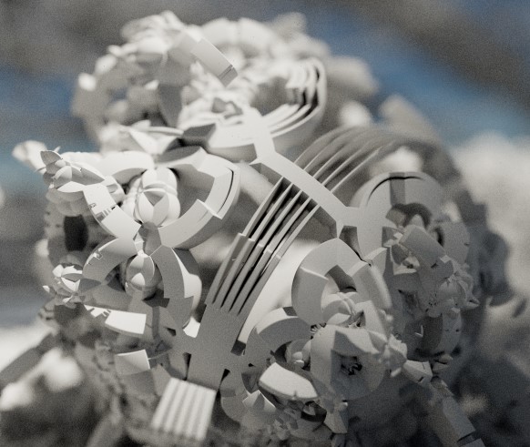

Completely diffuse material (click for large version)

How to solve the rendering equation

An integral is a continuous quantity, which we must turn into something discrete before we can handle it on the computer.

To evaluate the integral, we will use Monte Carlo sampling, which is a very simple: to provide an estimate for an integral, we will take a number of samples and use the average values of these samples multiplied by the integration interval length.

\(
\int_a^b f(x)dx \approx \frac{b-a}{N}\sum _{i=1}^N f(X_i)
\)
 
If we apply this to our diffuse rendering equation above, we get the following discrete summation:

\(
\begin{align}
L_{out}(\vec\omega_o) &= \int (Albedo/\pi)*L_{in}(\vec\omega_i)cos(\theta)d\vec\omega_i \\
& = \frac{2\pi}{N}\sum_{\vec\omega_i} (\frac{Albedo}{\pi}) L_{in}(\vec\omega_i) (\vec{n} \cdot \vec\omega_i) \\
& = \frac{2 Albedo}{N}\sum_{\vec\omega_i} L_{in}(\vec\omega_i) (\vec{n} \cdot \vec\omega_i)
\end{align}
\)
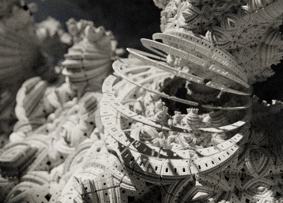

Test render (click for large version)

Building a path tracer (in GLSL)

Now we are able to build a simple path tracer for diffuse materials. All we need to do is to shoot rays starting from the camera, and when a ray hits a surface, we will choose a random direction in the hemisphere defined by the surface normal. We will continue with this until we hit a light source. Each time the ray changes direction, we will modulate the light intensity by the factor found above:

\(
2*Color*Albedo*L_{in}(\vec\omega_i) (\vec{n} \cdot \vec\omega_i)
\)
 
The idea is to repeat this many times for each pixel, and then average the samples. This is why the sum and the division by N is no longer present in the formula. Also notice, that we have added a (material specific) color. Until now we have assumed that our materials handled all wavelengths the same way, but of course some materials absorb some wavelengths, while reflecting others. We will describe this using a three-component material color, which will modulate the light ray at each surface intersection.

All of this boils down to very few lines of codes:

vec3 color(vec3 from, vec3 dir)
{
  vec3 hit = vec3(0.0);
  vec3 hitNormal = vec3(0.0);
	
  vec3 luminance = vec3(1.0);
  for (int i=0; i < RayDepth; i++) {
    if (trace(from,dir,hit,hitNormal)) {
       dir = getSample(hitNormal); // new direction (towards light)
       luminance *= getColor()*2.0*Albedo*dot(dir,hitNormal);
       from = hit + hitNormal*minDist*2.0; // new start point
    } else {
       return luminance * getBackground( dir );
    }
  }
  return vec3(0.0); // Ray never reached a light source
}

The getBackground() method simulates the light sources in a given direction (i.e. infinitely far away). As we will see below, this fits nicely together with using Image Based Lighting.

But even when implementing getBackground() as a simple function returning a constant white color, we can get very nice images:

and

The above images were lightened only a constant white dome light, which gives the pure ambient occlusion like renders seen above.

Sampling the hemisphere in GLSL

The code above calls a 'getSample' function to sample the hemisphere.

       dir = getSample(hitNormal); // new direction (towards light)

This can be a bit tricky. There is a nice formula for \(cos^n\) sampling of a hemisphere in the GI compendium (equation 36), but you still need to align the hemisphere with the surface normal. And you need to be able to draw uniform random numbers in GLSL, which is not easy.

Below I use the standard approach of putting a seed into a noisy function. The seed should depend on the pixel coordinate and the sample number. Here is some example code:

vec2 seed = viewCoord*(float(subframe)+1.0);

vec2 rand2n() {
    seed+=vec2(-1,1);
	// implementation based on: lumina.sourceforge.net/Tutorials/Noise.html
    return vec2(fract(sin(dot(seed.xy ,vec2(12.9898,78.233))) * 43758.5453),
		fract(cos(dot(seed.xy ,vec2(4.898,7.23))) * 23421.631));
};

vec3 ortho(vec3 v) {
    //  See : http://lolengine.net/blog/2013/09/21/picking-orthogonal-vector-combing-coconuts
    return abs(v.x) > abs(v.z) ? vec3(-v.y, v.x, 0.0)  : vec3(0.0, -v.z, v.y);
}

vec3 getSampleBiased(vec3  dir, float power) {
	dir = normalize(dir);
	vec3 o1 = normalize(ortho(dir));
	vec3 o2 = normalize(cross(dir, o1));
	vec2 r = rand2n();
	r.x=r.x*2.*PI;
	r.y=pow(r.y,1.0/(power+1.0));
	float oneminus = sqrt(1.0-r.y*r.y);
	return cos(r.x)*oneminus*o1+sin(r.x)*oneminus*o2+r.y*dir;
}

vec3 getSample(vec3 dir) {
	return getSampleBiased(dir,0.0); // <- unbiased!
}

vec3 getCosineWeightedSample(vec3 dir) {
	return getSampleBiased(dir,1.0);
}

Importance Sampling

Now there are some tricks to improve the rendering a bit: Looking at the formulas above, it is clear that light sources in the surface normal direction will contribute the most to the final intensity (because of the \( \vec{n} \cdot \vec\omega_i \) term).

This means we might want sample more in the surface normal directions, since these contributions will have a bigger impact on the final average. But wait: we are estimating an integral using Monte Carlo sampling. If we bias the samples towards the higher values, surely our estimate will be too large. It turns out there is a way around that: it is okay to sample using a non-uniform distribution, as long as we divide the sample value by the probability density function (PDF).

Since we know the diffuse term is modulated by the \( \vec{n} \cdot \vec\omega_i = cos(\theta) \), it makes sense to sample from a non-uniform cosine weighted distribution. According to GI compendium (equation 35), this distribution has a PDF of \( cos(\theta) / \pi \), which we must divide by, when using cosine weighted sampling. In comparison, the uniform sampling on the hemisphere we used above, can be thought of either to be multiplied by the integral interval length (\( 2\pi \)), or diving by a constant PDF of \( 1 / 2\pi \).

If we insert this, we end up with a simpler expression for the cosine weighted sampling, since the cosine terms cancel out:

vec3 color(vec3 from, vec3 dir)
{
  vec3 hit = vec3(0.0);
  vec3 hitNormal = vec3(0.0);
	
  vec3 luminance = vec3(1.0);
  for (int i=0; i < RayDepth; i++) {
    if (trace(from,dir,hit,hitNormal)) {
       dir =getCosineWeightedSample(hitNormal);
       luminance *= getColor()*Albedo;
       from = hit + hitNormal*minDist*2.0; // new start point
    } else {
       return luminance * getBackground( dir );
    }
  }
  return vec3(0.0); // Ray never reached a light source
}

Image Based Lighting

It is now trivial to replace the constant dome light, with Image Based Lighting: just lookup the lighting from a panoramic HDR image in the 'getBackground(dir)' function.

This works nicely, at least if the environment map is not varying too much in light intensity. Here is an example:


Stereographic 4D Quaternion system (click for large version)

If, however, the environment has small, strong light sources (such as a sun), the path tracing will converge very slowly, since we are not likely to hit these by chance. But for some IBL images this works nicely - I usually use a filtered (blurred) image for lighting, since this will reduce noise a lot (though the result is not physically correct). The sIBL archive has many great free HDR images (the ones named '*_env.hdr' are prefiltered and useful for lighting).

Direct Lighting / Next Event Estimation

But without strong, localized light sources, there will be no cast shadows - only ambient occlusion like contact shadows. So how do we handle strong lights?
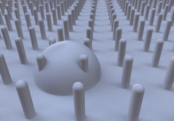

Test scene with IBL lighting

Let us consider the sun for a moment.

The sun has an angular diameter of 32 arc minutes, or roughly 0.5 degrees. How much of the hemisphere is this? The solid angle (which corresponds to the area covered of a unit sphere) is given by:

\(
\Omega = 2\pi (1 - \cos {\theta} )
\)
 
where \( \theta \) is half the angular diameter. Using this we get that the sun covers roughly \( 6*10^{-5} \) steradians or around 1/100000 of the hemisphere surface. You would actually need around 70000 samples, before there is even a 50% chance of a pixel actually catching some sun light (using \( 1-(1-10^{-5})^{70000} \approx 50\% \)).
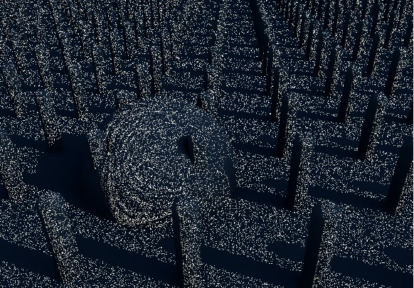

Test scene: naive path tracing of a sun like light source (10000 samples per pixel!)

Obviously, we need to bias the sampling towards the important light sources in the scene - similar to what we did earlier, when we biased the sampling to follow the BRDF distribution.

One way to do this, is Direct Lighting or Next Event Estimation sampling. This is a simple extension: instead of tracing the light ray until we hit a light source, we send out a test ray in the direction of the sun light source at each surface intersection.


Test scene with direct lighting (100 samples per pixel)

Here is some example code:

vec3 getConeSample(vec3 dir, float extent) {
        // Formula 34 in GI Compendium
	dir = normalize(dir);
	vec3 o1 = normalize(ortho(dir));
	vec3 o2 = normalize(cross(dir, o1));
	vec2 r =  rand2n();
	r.x=r.x*2.*PI;
	r.y=1.0-r.y*extent;
	float oneminus = sqrt(1.0-r.y*r.y);
	return cos(r.x)*oneminus*o1+sin(r.x)*oneminus*o2+r.y*dir;
}

vec3 color(vec3 from, vec3 dir)
{
  vec3 hit = vec3(0.0);
  vec3 direct = vec3(0.0);
  vec3 hitNormal = vec3(0.0);
	
  vec3 luminance = vec3(1.0);
  for (int i=0; i < RayDepth; i++) {
    if (trace(from,dir,hit,hitNormal)) {
       dir =getCosineWeightedSample(hitNormal);
       luminance *= getColor()*Albedo;
       from = hit + hitNormal*minDist*2.0; // new start point

       // Direct lighting
       vec3 sunSampleDir = getConeSample(sunDirection,1E-5);
       float sunLight = dot(hitNormal, sunSampleDir);
       if (sunLight>0.0 && !trace(hit + hitNormal*2.0*minDist,sunSampleDir)) {
           direct += luminance*sunLight*1E-5;
       }
    } else {
       return direct + luminance*getBackground( dir );
    }
  }
  return vec3(0.0); // Ray never reached a light source
}

The 1E-5 factor is the hemisphere area covered by the sun. Notice, that you might run into precision errors with the single-precision floats used in GLSL when doing these calculations. For instance, on my graphics card, cos(0.4753 degrees) is exactly equal to 1.0, which means a physically sized sun can easily introduce large numerical errors (remember the sun is roughly 0.5 degrees).

Sky model

To provide somewhat more natural lighting, an easy improvement is to combine the sun light with a blue sky dome.

A slightly more complex model is the Preetham sky model, which is a physically based model, taking different kinds of scattering into account. Based on the code from Simon Wallner I implemented a Preetham model in Fragmentarium.

Here is an animated example, showing how the color of the sun light changes during the day:

Path tracing test from Syntopia (Mikael H. Christensen) on Vimeo.

Fractals

Now finally, we are ready to apply path tracing to fractals. Technically, there is not much new to this - I have previously covered how to do the ray-fractal intersection in this series of blog posts: Distance Estimated 3D fractals.

So the big question is whether it makes sense to apply path tracing to fractals, or whether the subtle details of multiple light bounces are lost on the complex fractal surfaces. Here is the Mandelbulb, rendered with the sky model:


Path traced Mandelbulb (click for larger version)

Here path tracing provides a very natural and pleasant lighting, which improves the 3D perceptions.

Here are some more comparisons of complex geometry:

Default ray tracer in Fragmentarium


Path traced in Fragmentarium

And another one:

Default ray tracer in Fragmentarium


Path traced in Fragmentarium

What's the catch?

The main concern with path tracing is of course the rendering speed, which I have not talked much about, mainly because it depends on a lot of factors, making it difficult to give a simple answer.

First of all, the images above are distance estimated fractals, which means they are a lot slower to render than polygons (at least of you have a decent spatial acceleration structure for the polygons, which is surprisingly difficult to implement on a GPU). But let me give some numbers anyway.

In general, the rendering speed will be (roughly) proportional to the number of pixels, the FLOPS of the GPU, and the number of samples per pixel.

On my laptop (a mobile mid-range NVIDIA 850M GPU) the Mandelbulb image above took 5 minutes to render at 2442x1917 resolution (with 100 samples per pixel). The simple test scene above took 30 seconds at the same resolution (with 100 samples per pixel). But remember, that since we can show the render progressively, it is still possible to use this at interactive speeds.

What about the ray lengths (the number of light bounces)?

Here is a comparison as an animated GIF, showing direct light only (the darkest), followed by one internal light bounce, and finally two internal light bounces:
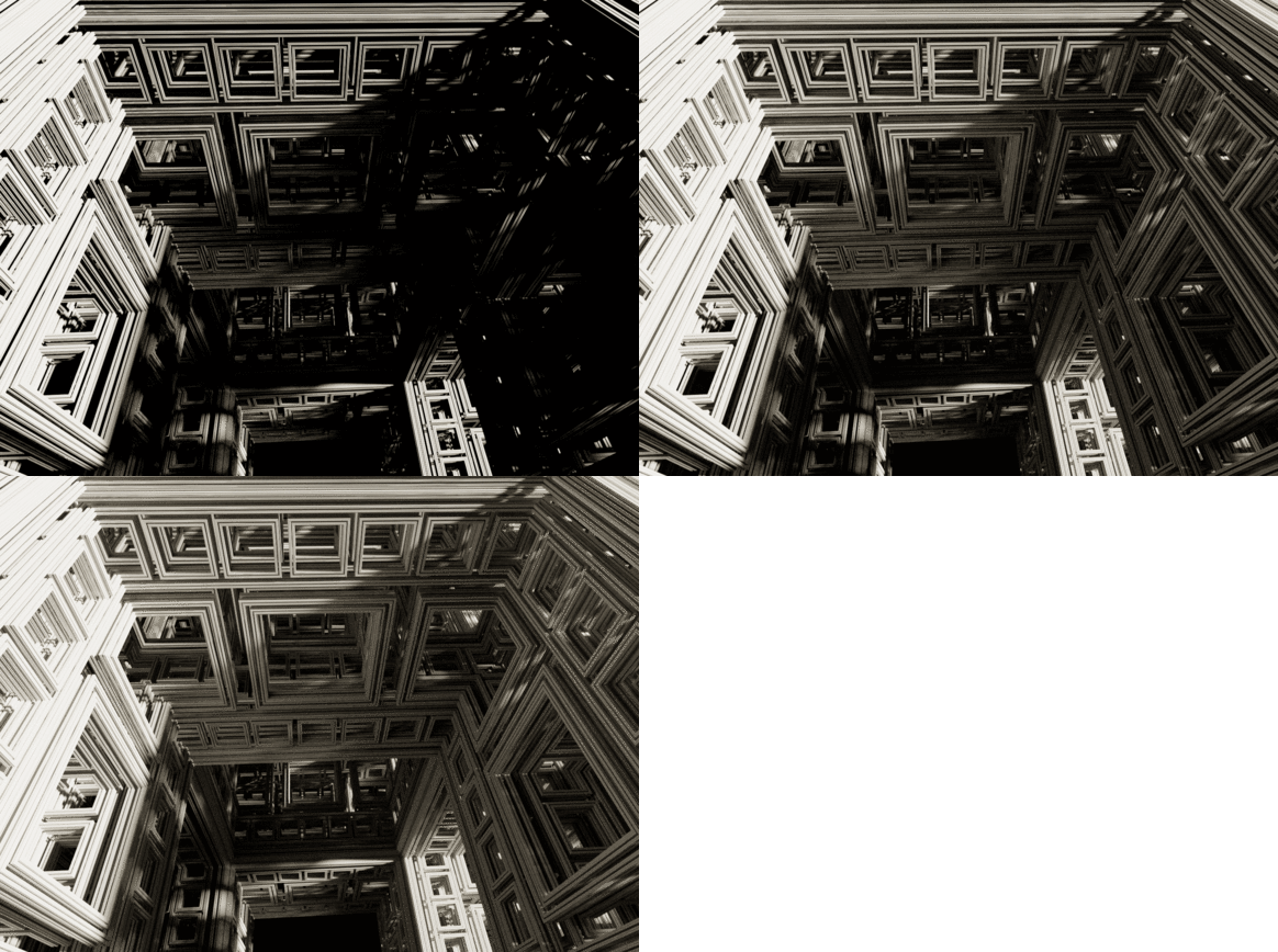
In terms of speed one internal bounce made the render 2.2x slower, while two bounces made it 3.5x slower. It should be noted that the visual effect of adding additional light bounces is normally relatively small - I usually use only a single internal light bounce.

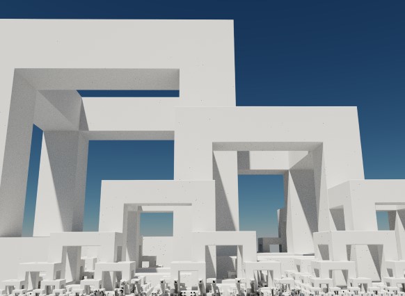
Even though the images above suggests that path tracing is a superior technique, it is also possible to create good looking images in Fragmentarium with the existing ray tracers. For instance, take a look at this image:


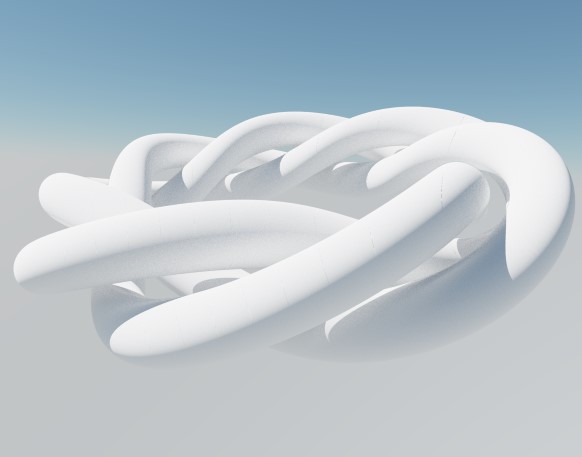
(taken from the Knots and Polyhedra series)

It was ray traced using the 'Soft-Raytracer.frag', and I was not able to improve the render using the Path tracer. Having said that, the Soft-Raytracer is also a multi-sample ray tracer which has to use lots of samples to produce the nice noise-free soft shadows.

References

The Fragmentarium path tracers are still Work-In-Progress, but they can be downloaded here:

Sky-Pathtracer.frag (which needs the Preetham model: Sunsky.frag).

and the image based lighting one:

IBL-Pathtracer.frag

The path tracers can be used by replacing an existing ray tracer '#include' in any Fragmentarium .frag file.

External resources

GI Total Compendium - very valuable collection of all formulas needed for ray tracing.

Vilém Otte's Bachelor Thesis on GPU Path Tracing is a good introduction.

Disney's BRDF explorer - Interactive display of different BRDF models - many examples included. The BRDF definitions are short GLSL snippets making them easy to use in Fragmentarium!

Inigo Quilez's path tracer was the first example I saw of using GPU path tracing of fractals.

Evan Wallace - the first WebGL Path tracer I am aware of.

Brigade is probably the most interesting real time path tracer: Vimeo video and paper.

I would have liked to talk a bit about unbiased and consistent rendering, but I don't understand these issues properly yet. It should be said, however, that since the examples I have given terminate after a fixed number of ray bounces, they will not converge to a true solution of the rendering equation (and, are thus both biased and inconsistent). For consistency, a better termination criterion, such as russian roulette termination, is needed.
Distance Estimated 3D Fractals (V): The Mandelbulb & Different DE Approximations

Previous posts: part I, part II, part III and part IV.

The last post discussed the distance estimator for the complex 2D Mandelbrot:

(1)  \(DE=0.5*ln(r)*r/dr\),

with ‘dr’ being the length of the running (complex) derivative:

(2)  \(f’_n(c) = 2f_{n-1}(c)f’_{n-1}(c)+1\)

In John Hart’s paper, he used the exact same form to render a Quaternion system (using four-component Quaternions to keep track of the running derivative). In the paper, Hart never justified why the complex Mandelbrot formula also should be valid for Quaternions. A proof of this was later given by Dang, Kaufmann, and Sandin in the book Hypercomplex Iterations: Distance Estimation and Higher Dimensional Fractals (2002).

I used the same distance estimator formula, when drawing the 3D hypercomplex images in the last post – it seems to be quite generic and applicable to most polynomial escape time fractal. In this post we will take a closer look at how this formula arise.

The Mandelbulb

But first, let us briefly return to the 2D Mandelbrot equation: \(z_{n+1} = z_{n}^2+c\). Now, squaring complex numbers has a simple geometric interpretation: if the complex number is represented in polar coordinates, squaring the number corresponds to squaring the length, and doubling the angle (to the real axis).

This is probably what motivated Daniel Nylander (Twinbee) to investigate what happens when turning to spherical 3D coordinates and squaring the length and doubling the two angles here. This makes it possible to get something like the following object:


On the image above, I made made some cuts to emphasize the embedded 2D Mandelbrot.

Now, this object is not much more interesting than the triplex and Quaternion Mandelbrot from the last post. But Paul Nylander suggested that the same approach should be used for a power-8 formula instead: \(z_{n+1} = z_{n}^8+c\), something which resulted in what is now known as the Mandelbulb fractal:

The power of eight is somewhat arbitrary here. A power seven or nine object does not look much different, but unexpectedly these higher power objects display a much more interesting structure than their power two counterpart.

Here is some example Mandelbulb code:

float DE(vec3 pos) {
	vec3 z = pos;
	float dr = 1.0;
	float r = 0.0;
	for (int i = 0; i < Iterations ; i++) {
		r = length(z);
		if (r>Bailout) break;
		
		// convert to polar coordinates
		float theta = acos(z.z/r);
		float phi = atan(z.y,z.x);
		dr =  pow( r, Power-1.0)*Power*dr + 1.0;
		
		// scale and rotate the point
		float zr = pow( r,Power);
		theta = theta*Power;
		phi = phi*Power;
		
		// convert back to cartesian coordinates
		z = zr*vec3(sin(theta)*cos(phi), sin(phi)*sin(theta), cos(theta));
		z+=pos;
	}
	return 0.5*log(r)*r/dr;
}

It should be noted, that several versions of the geometric formulas exists. The one above is based on doubling angles for spherical coordinates as they are defined on Wikipedia and is the same version as Quilez has on his site. However, several places this form appears:

float theta = asin( z.z/r );
float phi = atan( z.y,z.x );
... 
z = zr*vec3( cos(theta)*cos(phi), cos(theta)*sin(phi), sin(theta) );

which results in a Mandelbulb object where the poles are similar, and where the power-2 version has the nice 2D Mandelbrot look depicted above.

I’ll not say more about the Mandelbulb and its history, because all this is very well documented on Daniel White’s site, but instead continue to discuss various distance estimators for it.

So, how did we arrive at the distance estimator in the code example above?

Following the same approach as for the 4D Quaternion Julia set, we start with our iterative function:

\(f_n(c) = f_{n-1}^8(c) + c, f_0(c) = 0\)

 
Deriving this function (formally) with respect to c, gives

(3)   \(f’_n(c) = 8f_{n-1}^7(c)f’_{n-1}(c)+1\)

where the functions above are ‘triplex’ (3 component) valued. But we haven’t defined how to multiply two spherical triplex numbers. We only know how to square them! And how do we even derive a vector valued function with respect to a vector?

The Jacobian Distance Estimator

Since we have three different function components, which we can derive with three different number components, we end up with nine possible scalar derivatives. These may be arranged in a Jacobian matrix:
 
\(
J = \begin{bmatrix}
\frac {\partial f_x}{\partial x} & \frac {\partial f_x}{\partial y} & \frac {\partial f_x}{\partial z} \\
\frac {\partial f_y}{\partial x} & \frac {\partial f_y}{\partial y} & \frac {\partial f_y}{\partial z} \\
\frac {\partial f_z}{\partial x} & \frac {\partial f_z}{\partial y} & \frac {\partial f_z}{\partial z}
\end{bmatrix}
\)
 
The Jacobian behaves like similar to the lower-dimensional derivatives, in the sense that it provides the best linear approximation to F in a neighborhood of p:
 
(4)   \(
F(p+dp) \approx F(p) + J(p)dp
\)
 
In formula (3) above this means, we have to keep track of a running matrix derivative, and use some kind of norm for this matrix in the final distance estimate (formula 1).

But calculating the Jacobian matrix above analytically is tricky (read the comments below from Knighty and check out his running matrix derivative example in the Quadray thread). Luckily, other solutions exist.

Let us start by considering the complex case once again. Here we also have a two-component function derived by a two-component number. So why isn’t the derivative of a complex number a 2×2 Jacobian matrix?

It turns out that for a complex function to be complex differentiable in every point (holomorphic), it must satisfy the Cauchy Riemann equations. And these equations reduce the four quantities in the 2×2 Jacobian to just two numbers! Notice, that the Cauchy Riemann equations are a consequence of the definition of the complex derivative in a point p: we require that the derivative (the limit of the difference) is the same, no matter from which direction we approach p (see here). Very interestingly, the holomorphic functions are exactly the functions that are conformal (angle preserving) – something which I briefly mentioned (see last part of part III) is considered a key property of fractal transformations.

What if we only considered conformal 3D transformation? This would probably imply that the Jacobian matrix of the transformation would be a scalar times a rotation matrix (see here, but notice they only claim the reverse is true). But since the rotational part of the matrix will not influence the matrix norm, this means we would only need to keep track of the scalar part – a single component running derivative. Now, the Mandelbulb power operation is not a conformal transformation. But even though I cannot explain why, it is still possible to define a scalar derivative.

The Scalar Distance Estimator

It turns out the following running scalar derivative actually works:

(5)   \(dr_n = 8|f_{n-1}(c)|^7dr_{n-1}+1\)

where ‘dr’ is a scalar function. I’m not sure who first came up with the idea of using a scalar derivative (but it might be Enforcer, in this thread.) – but it is interesting, that it works so well (it also works in many other cases, including for Quaternion Julia system). Even though I don’t understand why the scalar approach work, there is something comforting about it: remember that the original Mandelbulb was completely defined in terms of the square and addition operators. But in order to use the 3-component running derivative, we need to able to multiply two arbitrary ‘triplex’ numbers! This bothered me, since it is possible to draw the Mandelbulb using e.g. a 3D voxel approach without knowing how to multiply arbitrary numbers, so I believe it should be possible to formulate a DE-approach, that doesn’t use this extra information. And the scalar approach does exactly this.

The escape length gradient approximation

Let us return to formula (1) above:

(1)  \(DE=0.5*ln(r)*r/dr\),

The most interesting part is the running derivative ‘dr’. For the fractals encountered so far, we have been able to find analytical running derivatives (both vector and scalar valued), but as we shall see (when we get to the more complex fractals, such as the hybrid systems) it is not always possible to find an analytical formula.

Remember that ‘dr’ is the length of the f'(z) (for complex and Quaternion numbers). In analogy with the complex and quaternion case, the function must be derived with regard to the 3-component number c. Deriving a vector-valued function with regard to a vector quantity suggests the use of a Jacobian matrix. Another approach is to take the gradient of the escape length: \(dr=|\nabla |z_{n}||\) – while it is not clear to me why this is valid, it work in many cases as we will see:

David Makin and Buddhi suggested (in this thread) that instead of trying to calculate a running, analytical derivative, we could use an numerical approximation, and calculate the above mentioned gradient using the finite forwarding method we also used when calculating a surface normal in post II.

The only slightly tricky point is, that the escape length must be evaluated for the same iteration count, otherwise you get artifacts. Here is some example code:

int last = 0;
float escapeLength(in vec3 pos)
{
	vec3 z = pos;
	for( int i=1; i Bailout && last==0) || (i==last))
		{
			last = i;
			return length(z);
		}
	}	
	return length(z);
}

float DE(vec3 p) {
	last = 0;
	float r = escapeLength(p);
	if (r*r<Bailout) return 0.0;
	gradient = (vec3(escapeLength(p+xDir*EPS), escapeLength(p+yDir*EPS), escapeLength(p+zDir*EPS))-r)/EPS;
	return 0.5*r*log(r)/length(gradient);
}

Notice the use of the ‘last’ variable to ensure that all escapeLength’s are evaluated at the same iteration count. Also notice that ‘gradient’ is a global varible – this is because we can reuse the normalized gradient as an approximation for our surface normal and save some calculations.

The approach above is used in both Mandelbulber and Mandelbulb 3D for the cases where no analytical solution is known. On Fractal Forums it is usually refered to as the Makin/Buddhi 4-point Delta-DE formula.

The potential gradient approximation

Now we need to step back and take a closer look at the origin of the Mandelbrot distance estimation formula. There is a lot of confusion about this formula, and unfortunately I cannot claim to completely understand all of this myself. But I’m slowly getting to understand bits of it, and want to share what I found out so far:

Let us start by the original Hart paper, which introduced the distance estimation technique for 3D fractals. Hart does not derive the distance estimation formula himself, but notes that:

Now, I haven’t talked about this potential function, G(z), that Hart mentions above, but it is possible to define a potential with the properties that G(Z)=0 inside the Mandelbrot set, and positive outside. This is the first thing that puzzled me: since G(Z) tends toward zero near the border, the “log G(Z)” term, and hence the entire term will become negative! As it turns out, the “log” term in the Hart paper is wrong. (And also notice that his formula (8) is wrong too – he must take the norm of complex function f(z) inside the log function – otherwise the distance will end up being complex too)

In The Science of Fractal Images (which Hart refers to above) the authors arrive at the following formula, which I believe is correct:

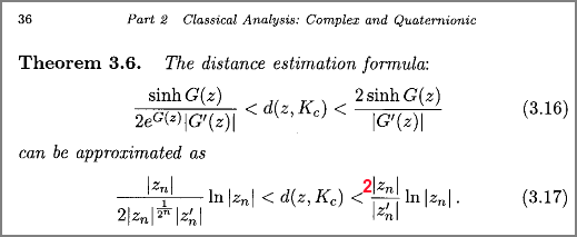
Similar, in Hypercomplex Iterations the authors arrive at the same formula:

But notice that formula (3.17) is wrong here! I strongly believe it misses a factor two (in their derivation they have \(sinh(z) \approx \frac{z}{2}\) for small z – but this is not correct: \(sinh(z) \approx z\) for small z).

The approximation going from (3.16) to (3.17) is only valid for points close to the boundary (where G(z) approaches zero). This is no big problem, since for points far away we can restrict the maximum DE step, or put the object inside a bounding box, which we intersect before ray marching.

It can be shown that \(|Z_n|^{1/2^n} \to 1\) for \(n \to \infty\). By using this we end up with our well-known formula for the lower bound from above (in a slightly different notation):

(1)  \(DE=0.5*ln(r)*r/dr\),

Instead of using the above formula, we can work directly with the potential G(z). For \(n \to \infty\), G(z) may be approximated as \(G(z)=log(|z_n|)/power^n\), where ‘power’ is the polynomial power (8 for Mandelbulb). (This result can be found in e.g. Hypercomplex Iterations p. 37 for quadratic functions)

We will approximate the length of G'(z) as a numerical gradient again. This can be done using the following code:

float potential(in vec3 pos)
{
	vec3 z = pos;
	for(int i=1; i Bailout) return log(length(z))/pow(Power,float(i));
	}	
	return 0.0;	
}

float DE(vec3 p) {
	float pot = potential(p);
	if (pot==0.0) return 0.0;
	gradient = (vec3(potential(p+xDir*EPS), potential(p+yDir*EPS), potential(p+zDir*EPS))-pot)/EPS;
	return (0.5/exp(pot))*sinh(pot)/length(gradient);
}

Notice, that this time we do not have to evaluate the potential for the same number of iterations. And again we can store the gradient and reuse it as a surface normal (when normalized).


A variant using Subblue’s radiolari tweak

Quilez’ Approximation

I arrived at the formula above after reading Iñigo Quilez’ post about the Mandelbulb. There are many good tips in this post, including a fast trigonometric version, but for me the most interesting part was his DE approach: Quilez used a potential based DE, defined as:

\(DE(z) = \frac{G(z)}{|G'(z)|} \)
 
This puzzled me, since I couldn’t understand its origin. Quilez offers an explanation in this blog post, where he arrives at the formula by using a linear approximation of G(z) to calculate the distance to its zero-region. I’m not quite sure, why this approximation should be justified, but it seems a bit like an example of Newtons method for root finding. Also, as Quilez himself notes, he is missing a factor 1/2.

But if we start out by formula (3.17) above, and notes that \(sinh(G(z)) \approx G(z)\) for small G(z) (near the fractal boundary) , and that \(|Z_n|^{1/2^n} \to 1\) for \(n \to \infty\) we arrive at:

\(DE(z) = 0.5*\frac{G(z)}{|G'(z)|} \)
 
(And notice that the same two approximations are used when arriving at our well-known formula (1) at the top of the page).

Quilez’ method can be implemented using the previous code example and replacing the DE return value simply by:

return 0.5*pot/length(gradient);

If you wonder how these different methods compare, here are some informal timings of the various approaches (parameters were adjusted to give roughly identical appearances):

Sinh Potential Gradient (my approach) 1.0x
Potential Gradient (Quilez) 1.1x
Escape Length Gradient (Makin/Buddhi) 1.1x
Analytical 4.1x

The three first methods all use a four-point numerical approximation of the gradient. Since this requires four calls to the iterative function (which is where most of the computational time is spent), they are around four times slower than the analytical solution, that only uses one evaluation.

My approach is slightly slower than the other numerical approaches, but is also less approximated than the others. The numerical approximations do not behave in the same way: the Makin/Buddhi approach seems more sensible to choosing the right EPS size in the numerical approximation of the gradient.

As to which function is best, this requires some more testing on various systems. My guess is, that they will provide somewhat similar results, but this must be investigated further.


The Mandelbulb can also be drawn as a Julia fractal.

Some final notes about Distance Estimators

Mathematical justification: first note, that the formulas above were derived for complex mathematics and quadratic systems (and extended to Quaternions and some higher-dimensional structures in Hypercomplex Iterations). These formulas were never proved for exotic stuff like the Mandelbulb triplex algebra or similar constructs. The derivations above were included to give a hint to the origin and construction of these DE approximations. To truly understand these formula, I think the original papers by Hubbard and Douady, and the works by John Willard Milnor should be consulted – unfortunately I couldn’t find these online. Anyway, I believe a rigorous approach would require the attention of someone with a mathematical background.

Using a lower bound as a distance estimator. The formula (3.17) above defines lower and upper bounds for a given point to the boundary of the Mandelbrot set. Throughout this entire discussion, we have simply used the lower bound as a distance estimate. But a lower bound is not good enough as a distance estimate. This can easily be realized since 0 is always a lower bound of the true distance. In order for our sphere tracing / ray marching approach to work, the lower bound must converge towards to the true distance, as it approaches zero! In our case, we are safe, because we also have an upper bound which is four times the lower bound (in the limit where the exp(G(z)) term disappears). Since the true distance must be between the lower and upper bound, the true distance converges towards the lower bound, as the lower bound get smaller.

DE’s are approximations. All our DE formulas above are only approximations – valid in the limit \(n \to \infty\), and some also only for point close to the fractal boundary. This becomes very apparent when you start rendering these structures – you will often encounter noise and artifacts. Multiplying the DE estimates by a number smaller than 1, may be used to reduce noise (this is the Fudge Factor in Fragmentarium). Another common approach is to oversample – or render images at large sizes and downscale.

Future directions. There is much more to explore and understand about Distance Estimators. For instance, the methods above use four-point numerical gradient estimation, but perhaps the primary camera ray marching could be done using directional derivatives (two point delta estimation), and thus save the four-point sampling for the non-directional stuff (AO, soft shadows, normal estimation). Automatic differentation with dual numbers (as noted in post II) may also be used to avoid the finite difference gradient estimation. It would be nice to have a better understanding of why the scalar gradients work.

The next blog post discusses the Mandelbox fractal.

Distance Estimated 3D Fractals (IV): The Holy Grail

Previous posts: part I, part II, and part III.

Despite its young age, the Mandelbulb is probably the most famous 3D fractal in existence. This post will examine how we can create a Distance Estimator for it. But before we get to the Mandelbulb, we will have to step back and review a bit of the history behind it.

The Search for the Holy Grail

The original Mandelbrot fractal is a two dimensional fractal based on the convergence properties of a series of complex numbers. The formula is very simple: for any complex number z, check whether the sequence iteratively defined by \(z_{n+1} = z_{n}^2+c\) diverges or not. The Mandelbrot set is defined as the set of points which do not diverge, that is, the points with a series that stays bounded within a given radius. The results can be depicted in the complex plane.

The question is how to extend this to three dimensions. The Mandelbrot set fits two dimensions, because complex numbers have two components. Can we find a similar number system for three dimensions?

The Mandelbrot formula involves two operations: adding numbers, and squaring them. Creating a n-component number where addition is possible is easy. This is what mathematicians refer to as a vector space. Component-wise addition will do the trick, and seems like the logical choice.

But the Mandelbrot formula also involves squaring a number, which requires a multiplication operator (a vector product) on the vector space. A vector space with a (bilinear) vector product is called an algebra over a field. The numbers in these kind of vector spaces are often called hypercomplex numbers.

To see why a three dimensional number system might be problematic, let us try creating one. We could do this by starting out with the complex numbers and introduce a third component, j. We will try to keep as many as possible of the characteristic properties of the complex and real numbers, such as distributivity, \(a*(b+c)=(a*b)+(a*c)\), and commutativity, \(a*b=b*a\). If we assume distributivity, we only need to specify how the units of the three components multiply. This can be illustrated in a multiplication table. Since we also assumed commutativity, such a table must be symmetric:

\(
\begin{bmatrix}
& \boldsymbol{1} & \boldsymbol{i} & \boldsymbol{j} \\
\boldsymbol{1} & 1 & i & j \\
\boldsymbol{i} & i & -1 & ?\\
\boldsymbol{j} & j & ? & ?
\end{bmatrix}
\)
 
For a well-behaved number system, anything multiplied by 1 is still one, and if we now require the real and imaginary components to behave as for the complex numbers, we only have three components left – the question marks in the matrix. I’ve rendered out a few of the systems, I encountered while trying arbitrary choices of the missing numbers in the matrix:

(Many people have explored various 3D component multiplication tables – see for instance Paul Nylander’s Hypercomplex systems for more examples).

Unfortunately, our toy system above fails to be associative (i.e. it is not always true, that \(a*(b*c) = (a*b)*c\)), as can be seen by looking at the equation \(i*(i*j) = (i*i)*j \Rightarrow i*x = -j\), which can not be satisfied no matter how we choose x.

It turns out that it is difficult to create a consistent number system in three dimensions. There simply is no natural choice. In fact, if we required that our number system allowed for a division operator, there is a theorem stating that only four such mathematical spaces are possible: the real numbers (1D), the complex numbers (2D), the quaternions (4D) and the octonions (8D). But no 3D systems.

But what about the 4D Quaternions? Back in 1982, Alan Norton published a paper showing a Quaternion Julia set made by displaying a 3D “slice” of the 4D space. Here is an example of a Quaternion Julia fractal:

Of course, in order to visualize a 4D object, you have to make some kind of dimensional reduction. The most common approach is to make a 3D cross-section, by simply keeping one of the four components at a fixed value.

If you wonder why you never see a Quaternion Mandelbrot image, the reason is simple. It is not very interesting because of its axial symmetry:

If you, however, make a rotation inside the iteration loop, you can get something more like a 3D Mandelbrot.

The Quaternion system (and the 3D hypercomplex systems above) are defined exactly as the 2D system – by checking if \(z_{n+1} = z_{n}^2+c\) converges or not.

But how do we draw a 3D image of these fractals? In contrast to the 2D case, where it is possible to build a 2D grid, and check inside each cell, building a 3D grid and checking each cell would be far too memory and time consuming for images in any decent resolution.

A distance estimator for quadratic systems.

While Alan Norton used a different rendering approach, a very elegant solution to this was found by John Hart et al in a 1989 paper: distance estimated rendering. As discussed in the previous posts, distance estimated rendering requires that we are able to calculate a lower bound to the distance from every point in space to our fractal surface! A first, this might seem impossible. But it turns out such a formula already was known for the 2D Mandelbrot set. A distance estimate can be found as:

(1)   \(DE=0.5*ln(r)*r/dr\)
 
Where ‘r’ is the escape time length, and ‘dr’ is the length of the running derivative. (The approximation is only exact in the limit where the number of iterations goes to infinity)

In order to define what we mean by the running derivative, we need a few extra definitions. For Mandelbrot sets, we study the sequence \(z_{n+1} = z_{n}^2+c\) for each point c. Let us introduce the function \(f_n(c)\), defined as the n’th entry for the sequence for the point c. By this definition, we have the following defining formula for the Mandelbrot set:

\(f_n(c) = f_{n-1}^2(c) + c, f_0(c) = 0\)
 
Deriving this function with respect to c, gives

(2)   \(f’_n(c) = 2f_{n-1}(c)f’_{n-1}(c)+1\)   (for Mandelbrot formula)
 
Similar, the Julia set is defined by choosing a fixed constant, d, in the quadratic formula, using c only as the first entry in our sequence:

\(f_n(c) = f_{n-1}^2(c) + d, f_0(c) = c\)
 
Deriving this function with respect to c, gives

(3)   \(f’_n(c) = 2f_{n-1}(c)f’_{n-1}(c)\)   (for Julia set formula)
 
which is almost the same result as for the Mandelbrot set, except for unit term. And now we can define the length of \(f_n\), and the running derivative \(f’_n\):
 
\(r = |f_n(c)|\) and \(dr = |f’_n(c)|\)
 
used in the formula (1) above. This formula was found by Douady and Hubbard in a 1982 paper (more info).


2D Julia set rendered using a distance estimator approach. This makes it possible to emphasize details, without having to use extensive oversampling.

Due to a constraint in WordPress, this post has reached its maximum length. The next post continues the discussion, and shows how the formula above can be used for other types of fractals than the 2D Mandelbrot.

Hybrid 3D Fractals

A lot of great images have been made of the Mandelbulb, the Mandelbox, and the various kaleidoscopic IFS’s (the non-platonic non-solids). And it turns out that by combining these formulas (and stirring a few assorted functions into the mix), a variety of new, amazing, and surprising forms emerge.

I’m currently working on making it easier to combine different formulas in Fragmentarium – but until I get something released, here is a collection of images and movies created by Mandelbulb 3D (Windows, free) and Mandelbulber (Windows, free, open-source), that illustrates the beauty and diversity of these hybrid systems. Be sure to view the large versions by following the links. The images were all found at Fractal Forums.

Videos


Buddhi – Mandelbox and Flying Lights


Jérémie Brunet (Bib) – Weird Planet II


Jérémie Brunet (Bib) – Like in a dream II

Images


Lenord – Pray your Gods


Tomot – It’s a jungle out there


Lenord – J.A.R.


MarkJayBee – Security Mechanisms


Fractal00 – Alien Stones


Kr0mat1k – Restructuration


BrutalToad – Jülchen

Folding Space II: Kaleidoscopic Fractals

Another type of interesting 3D fractal has appeared over at fractalforums.com: the Kaleidoscopic 3D fractals, introduced in this thread, by Knighty.

Once again these fractals are defined by investing the convergence properties of a simple function. And similar to the Mandelbox, the function is built around the concept of folds. Geometrically, a fold is simply a conditional reflection: you reflect a point in a plane, if it is located on the wrong side of the plane.

It turns out that just by using plane-folds and scaling, it is possible to create classic 3D fractals, such as the Menger cube and the Sierpinsky tetrahedron, and even recursive versions of the rest of the Platonic solids: the octahedron, the dodecahedron, and the icosahedron.


Example of a recursive dodecahedron

The kaleidoscopic fractals introduce an additional 3D rotation before and after the folds. It turns out that these perturbations introduce a rich variety of interesting and complex structures.

I’ve followed the thread and implemented most of the proposed systems by modifying Subblue’s Pixel Bender scripts.

Below are some of my images:

The Menger Sponge

My first attempts. Pixel Bender kept crashing on me, until I realized that there is a GPU timeout in Windows Vista (read this for a solution).


The Sierpinsky

Then I moved on to the Sierpinsky. The sequence below shows something characteristic for these fractals: the first slightly perturbed variations look artificial and synthetic, but when the system is distorted, it becomes organic and alive.


The Icosahedron

I also tried the octahedron and dodecahedron, but my favorite is the icosahedron. Especially knighty’s hollow variant.


Arbitrary Planes

One nice thing about these systems is, that you do not necessarily need to derive a complex distance estimator – you can also just modify the distance estimator code, and see what happens. These last two images were constructed by modifying existing distance estimators.

It will be interesting to see where this is going.

Many fascinating 3D fractals have appeared at fractalforums.com over the last few weeks. And GPU processing now makes it is possible to explore these systems in real-time.

A Few Links

…some old, some new.

The Demoscene

It was only a matter of time, before a Mandelbox would show up on the Demoscene:

Hochenergiephysik by Still is a 4K demo, featuring the Mandelbox. If 4KB sounds bloated, Still has also created a 1K demo: Futurism by Still.

And while we are at it, may I suggest these as well: The Cube by Farbrausch, Rove by Farbraush, and Agenda Circling Forth by Fairlight & Cncd.

New software

NodeBox 2.0 is out in a beta version. The big news is that it is now available for Windows. It also sports a graph-based GUI for patching nodes together.

Tacitus is a GUI for creating per-pixel GPU effects. In concept it is similar to Pixel Bender. It has a very nice look and feel, but a big short-coming is that it is not possible to directly edit the GPU scripts in the GUI – you have to compile your script to a plugin via an included compiler. Another feature I miss, is the ability to directly navigate the camera using the mouse on the viewport, instead of using sliders (something Pixel Bender also doesn’t support). But Tacitus is still in beta, and it will be interesting to see where it is going. It comes with a single plugin, a port of Subblue’s Mandelbulb Pixel Bender plugin. Tacitus is Windows only.

NeuroSystems Substance is an ‘Evolutionary and Organic Art Creator’. Some interesting concepts here, including a real-time global illumination raytracer (video here). Unfortunately, the raytracer is not part of the free viewer. Surprisingly, NeuroSystems impressive visualization technology seems to originate from SIMPLANT, a real-time 3D breast implant simulator. Substance is Windows only, and the full (non-free) versions should be released very soon.

Gifts for Geeks

A Calabi-Yau Manifold Crystal sculpture.


A Gömböc. “The ‘Gömböc’ is the first known homogenous object with one stable and one unstable equilibrium point, thus two equilibria altogether on a horizontal surface. It can be proven that no object with less than two equilibria exists.”

The Reality of Fractals

“… no one, not even Benoit Mandelbrot himself […] had any real preconception of the set’s extraordinary richness. The Mandelbrot set was certainly no invention of any human mind. The set is just objectively there in the mathematics itself. If it has meaning to assign an actual existence to the Mandelbrot set, then that existence is not within our mind, for no one can fully comprehend the set’s endless variety and unlimited complication.”

Roger Penrose (from The Road to Reality)

The recent proliferation of 3D fractals, in particular the Mandelbox and Mandelbulb, got me thinking about the reality of these systems. The million dollar question is whether we discover or construct these entities. Surely these systems give the impression of exploring uncharted territory, perhaps even looking into another world. But the same can be said for many traditional man-made works of art.

I started out by citing Roger Penrose. He is a mathematical Platonist, and believes that both the fractals worlds (such as the Mandelbrot set) and the mathematical truths (such as Fermat’s last theorem) are discovered. In his view, the mathematical truths have an eternal, unchanging, objective existence in some kind of Platonic ideal world, independent of human observers.

In Penrose’s model, there are three distinct worlds: the physical world, the mental world (our perception of the physical world), and the cryptic Platonic world. Even Penrose himself admits that the connections and interactions between these worlds are mysterious. And personally I cannot see any kind of evidence pointing in favor of this third, metaphysical world.


Designer World by David Makin

Roger Penrose is a highly renowned mathematician and physicist, and I value his opinions and works highly. In fact, it was one of his earlier books, The Emperors New Mind, that in part motivated me to become a physicist myself. But even though he is probably one of the most talented mathematicians living today, I am not convinced by his Platonist belief.

Personally, I subscribe to the less exotic formalist view: that the mathematical truths are the theorems we can derive by applying a set of deduction rules to a set of mathematical axioms. The axioms are not completely arbitrary, though. For instance, a classic mathematical discipline, such as Euclidean geometry, was clearly motivated by empirical observations of the physical world. The same does not necessarily apply to modern mathematical areas. For instance, Lobachevsky’s non-Euclidean geometry, was conceived by exploring the consequences of modifying one of Euclid’s fundamental postulates (interestingly non-Euclidean geometry later turned out to be useful in describing the physical world through Einstein’s general theory of relativity).

But if modern mathematics has become detached from its empirical roots, what governs the evolution of modern mathematics? Are all formal systems thus equally interesting to study? My guess is that most mathematicians gain some kind of intuition about what directions to pursue, based on a mixture of trends, historical research, and feedback from applied mathematics.


Mandelballs by Krzysztof Marczak [Mandelbox / Juliabulb mix]

Does my formalist position mean that I consider the Mandelbrot set to be a man-made creation, in the same category as a Picasso painting or a Bach concert? Not exactly. Because I do believe in a physical realism (in the sense that I believe in a objective, physical world independent of human existence), and since I do believe some parts of mathematics is inspired by this physical world and tries to model it, I believe some parts of mathematics can be attributed an objective status as well. But it is a weaker kind of objective existence: the mathematical models and structures used to describe reality are not persistent and ever-lasting, instead they may be refined and altered, as we progressively create models with greater predictive power. And I think this is the reason fractals often resemble natural structures and phenomena: because the mathematics used to produce the fractals was inspired by nature in the first place. Let me give another example:


Teeth by Jesse

Would a distant alien civilization come up with the same Mandelbrot images as we see? I think it is very likely. Any advanced civilization studying nature, would most likely have created models such as the natural numbers, the real numbers, and eventually the complex numbers. The complex numbers are extremely useful when modeling many physical phenomena, such as waves or electrodynamics, and complex numbers are essential in the description of quantum mechanics. And if this hypothetical civilization had computational power available, eventually someone would investigate the convergence of a simple, iterated system like z = z2 + c. So there would probably be a lot of overlapping mathematical structures. But there would also be differences: for instance the construction of the slightly more complex Mandelbox set contains several human-made design decisions, making it less likely to be invented by our distant civilization.

I think there is a connection to other areas of generative art as well. In the opening quote Penrose claims that no-one could have any real preconception of the Mandelbrot sets extraordinary richness. And the same applies to many generative systems: they are impossible to predict and often surprisingly complex and detailed. But this does not imply that they have a meta-physical Platonic origin. Many biological and physical systems share the same properties. And many of the most interesting generative systems are inspired by these physical or biological systems (for instance using models such as genetic algorithms, flocking behavior, cellular automata, reaction-diffusion systems, and L-systems).

Another point to consider is, that creating beautiful and interesting fractal images as the ones above, requires much more than a simple formula. It requires aesthetic intuition and skills to choose a proper palette, find an interesting camera location, and it takes many hours of formula parameter tweaking. I know this from my experiments with 3D fractals – I’m very rarely satisfied with my own results.

But to sum it all up: Even though fractals (and generative systems) may posses endless variety and unlimited complication, there is no need to call upon metaphysical worlds in order to explain them.

Folding Space: The Mandelbox Fractal

Over at fractalforums.com another interesting 3D fractal has emerged: the Mandelbox.

It originates from this thread, where it was introduced by Tglad (Tom Lowe). Similar to the original Mandelbrot set, an iterative function is applied to points in 3D space, and points which do not diverge are part of the set. The iterated function used for the Mandelbox set has a nice geometric interpretation: it corresponds to repeated folding operations.

In contrast to the organic presence of the Mandelbulbs, the Mandelbox has a very architectural and structural feel to it:


The Mandelbox probably owes it name to the cubic and square patterns that emerge at many levels:


It is also possible to create Julia Set variations:


Juliabox by ‘Jesse’ (click to see the large version of this fantastic image!)

Be sure to check out Tom Lowe’s Mandelbox site for more pictures and some technical background information, including links to a few (Windows only) software implementations.

I tried out the Ultra Fractal extension myself. This was my first encounter with Ultra Fractal, and it took me quite some time to figure out how to setup a Mandelbox render. For others, the following steps may help:

  1. Install Ultra Fractal (there is a free trial version).
  2. Choose ‘Options | Update Public Formulas…’ to get some needed dependencies.
  3. Install David Makin’s MMFwip3D package and install it into the Ultra Fractal formula folder – it is most likely located at “%userprofile%\Documents\Ultra Fractal 5\Formulas”.
  4. In principle, this is all you need. But the MMFwip3D formulas contain a vast number of parameters and settings. To get started try using some existing parameter set: this is a good starting point. In order to use these settings, simply select the text, copy it into the clipboard, and paste it into an Ultra Fractal fractal window.

The CPU-based implementations are somewhat slow, taking minutes to render even small images – but it probably won’t be long before a GPU-accelerated version appear: Subblue has already posted images of a PixelBender implementation in progress.

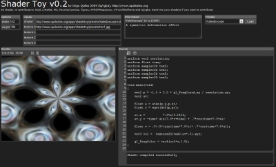
Shader Toy

For some time I’ve been wanting to play around with pixel (fragment) shaders, but I couldn’t find a proper playground.

Then I stumbled upon Shader Toy, by Inigo Quilez (whom I’ve mentioned several times on this blog). A couple of things make Shader Toy stand out:

It runs inside your browser. It uses the emerging WebGL standard, which is JavaScript bindings for OpenGL (ES) 2.0. OpenGL can be used directly inside a Canvas HTML element, including support for custom shaders. As Shader Toy demonstrates, this makes it possible to do some very impressive stuff, such as real-time GPU-accelerated raytracing inside an element on a web page.

The examples are great. While Shader Toy itself is mostly a thin wrapper around the WebGL functionality, the great thing about it is the example shaders: 2D fractals and Demo Scene effects, but also complex examples like the Slisesix 4K demo, and examples of raytracing, and complex fractals, like the Quaternion Julia set, and the Mandelbulb.

The only problem with WebGL is, that it is not supported by the current generation of browsers.

The good news is that the nightly builds of Firefox, Safari (WebKit), and Chromium (Google Chrome) all support it, and are quite easy to install: this is a good place for more information. If you use the Chromium builds, you don’t have to worry about messing up your existing browser configuration – the nightly builds are standalone versions and can be run without installation.

There are lots of complex shader tools out there: for instance, NVIDIAs FX Composer, AMDs Rendermonkey, TyphoonLabs OpenGL Shader Designer, and Lumina, but Shader Toy makes it very easy to get started with shaders. And it provides a rare insight into how those amazing 4K demos were made.

Mandelbulb Implementations

Several implementations have appeared since the Mandelbulb surfaced a couple of months ago.

The first public GPU implementation I know of was created by ‘cbuchner1’. It is based on a sample from NVIDIAs OptiX SDK, and features anaglyphic 3D, ambient occlusion, phong shading, reflection, and environment maps. It can be downloaded here (Windows only and requires a forum signup).


Example made with cbuchner1’s implementation

Very interestingly this binary runs on my laptops modest GeForce 8400M. I am a bit puzzled about this – NVIDIA state that the OptiX SDK requires a Quadro or a Tesla card, and I am not able to run the Julia OptiX demo, that cbuchner1s app is derived from.

Subblue has also created a Mandelbulb implementation, released as a Pixel Bender script and a Quartz composer plugin. A number of interesting customizations makes this my favorite choice: it is possible to explore negative and fractional powers, switch to Julia sets, and the lightning options can be fine-tuned. The only drawback is that Pixel Bender does not make it possible to directly rotate, zoom, and translate the camera – you have to rely on sliders for that.


Example created by Subblue.

Iñigo Quílez has also created a GPU implementation, but unfortunately he has not released any code yet. A couple of videos are available on Youtube, though: Part 1, Part 2, Part 3.


Quilez also discovered this intimate connection between the Shroud of Turin and the Mandelbulb.

The MathFuncRenderer also has a Mandelbulb implementation. I had a few quirks with this one – I had to install OpenAL, and the UI was quite non-responsive, but this may be due to my graphics card.

Another very interesting implementation is the GigaVoxels Mandelbulb: Whereas most implementations cast rays and use a distance estimator to speed up the ray marching, GigaVoxels use voxels stored into an Octree, which is populated on-the-fly.

For other implementations keep an eye on Fractal Forums Mandelbulb Implementation category.